
Overview of Primary Product


page 7
PIPE
DIAMETER
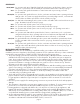
MAXIMUM EQUIVALENT PIPE FEET (BETWEEN
AIR BOOT™ AND DUCT TERMINATION)
ELBOW*
EQUIVALENT FEET
REDUCER OR INCREASER
EQUIVALENT FEET
4" 44' 7' -
5" 60' 9' (4" to 5") 3'
6" 90' 11' (4" to 6") 6'
*Note: Subtract the Elbow or reducer equivalent feet from the maximum equivalent feet to get maximum linear feet of pipe.
CV-4&5 INSTALLATION CLEARANCES TO COMBUSTIBLES
Max. Inlet Temperature Through-wall Clearance
Vent Pipe Clearances
Double Pipe System Single Pipe System
400ºF or Less
1
⁄2" min
1
⁄2" min 3" min
400ºF - 650ºF (US)
400ºF - 575ºF (Can)
1
⁄2" min
1" min 4" min
1
⁄2" min with sheet metal
liner
3" min with sheet
metal liner
*Caution: Air Tee Cover Plate must be in position on Air Tee when not providing combustion air.
NOTE: Vent pipe joints should be secured with at least three (3) sheet metal screws.
COMBUSTION AIR DUCT WORK INSTALLATION
A maximum of 30 linear feet of 4” duct pipe and two (2) 90° elbows at maximum firing rate may be used (44 1.
equivalent feet). Subtract 7 feet from the maximum linear feet for every additional 90° elbow added. Longer
pipe lengths require the use of a larger pipe between the VRV and the intake hood. It also requires the use of a
vent pipe increaser at the VRV and a reducer at the intake hood. (See Table 3)
Table 3
Table 4
NOTE: Try to run a minimum of 12 feet of duct to help temper the outside air being brought into burner.
INSTALLATION USING SINGLE WALL VENT PIPE (SEE TABLE 4)
Route the duct work from the VRV tee to the inlet vent termination with as few elbows as possible.2.
Secure and support the duct work for the design and weight of the material used, to prevent physical damage 3.
and separation of joints. For guidelines, refer to recognized national building codes or any local codes.
To reduce uncontrolled air leakage into the duct, tape all joints and seams using standard duct tape.4.
For appliances constructed with a combustion air inlet connection that do not come equipped with 1.
means of either (a) providing the burner with an alternate source of combustion air in the event of
blockage, or (b) safely preventing combustion in the event of a blockage: Install a Field Controls Vacuum
Relief Valve, model VRV (sold separately), in the combustion air piping from the air tee collar to the
appliance inlet connection, following the installation instructions included with the VRV. (See Figure 9)
This will allow combustion air to be drawn from within the structure (or a safe shutdown) if the venter
inlet becomes blocked.
For oil appliances without a combustion air inlet connection, install a Field Controls Airboot, series 2.
CAS-2, with the model appropriate for the particular burner model (see the Field Controls Contractor
Reference Guide for instructions on specifying the Airboot model). A VRV is included with the Airboot
and need not be purchased separately.
COMBUSTION AIR SYSTEM CONNECTIONS