
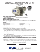
Overview of Primary Product


page 9
GENERAL INSTALLATION INSPECTION
Recommended procedures for safety inspection of an appliance in accordance with the National Fuel Gas
Code ANSI Z223.1. The following procedure will help evaluate the venting system. It is intended as a guide to
aid in determining that the venting system is properly installed and is in a safe condition for continuous use. This
procedure should be recognized as a generalized procedure which cannot anticipate all situations. Accordingly,
in some cases, deviation from this procedure may be necessary to determine safe operation of the equipment.
If it is determined that a condition exists which could result in unsafe operation, the appliance should be shut
off and the owner advised of the unsafe condition. Corrections must be made before the appliance is put into
continuous operation. The following steps should be followed in making a safety inspection.
Visually inspect the venting system for proper size and determine that there is no flue gas spillage, 1.
blockage, restriction, leakage, corrosion or other deficiency which could cause an unsafe operation.
Insofar as practical, close all building doors, fireplace dampers, windows, and all doors in area in which 2.
the appliance is located. Turn on clothes dryers, any exhaust fans, such as range hoods and bathroom
exhausters so they operate at maximum speed. Do not operate a summer exhaust fan. If, after completing
Steps 3 through 7 it is believed sufficient combustion air is not available, refer to the National Fuel Gas
Code ANSI Z223.1, or any applicable local codes for guidance.
Place in operation the appliance being inspected. Follow the lighting instructions and adjust thermostat so 3.
appliance will operate continuously.
Determine that the pilot or burner is operating properly and that the main burner ignition operates 4.
satisfactorily, by interrupting and re-establishing the electrical power of the appliance in any convenient
manner. Test the pilot or burner safety device to determine if it is operating properly by extinguishing the
pilot or disconnecting the flame safety circuit and pressure switch sensing tube from the pressure switch.
Visually determine that the main burner is burning properly; i.e., no floating, lifting or flashbacks. When 5.
performing smoke test on oil-fired systems, the burner should operate at a zero to a trace smoke. This can
indicate reduced available combustion air to burner.
If appliances are equipped with high and low flame control or flame modulation, check for proper main 6.
burner operation at low flame.
Test for spillage at draft hood or barometric draft control opening and burner inlet air location after 5 7.
minutes of main burner operation. Use a draft gauge, flame of a match or candle, smoke from a cigarette,
cigar or pipe. If spillage occurs, adequate air is not available. Shut off heating appliance thermostat and
check for spillage around the draft hood, barometric draft control or burner inlet air location after power
venter has stopped operation. If a flow reversal is noticed, house de-pressurization is occurring and make
up air is required. For oil-fired systems, this may be noticed by oil fume smell after post purge cycle.
Turn on all fuel burning appliances within the same room so that they will operate at their maximum input. 8.
Then repeat Steps 5 through 7.
Return doors, windows, exhaust fans, fireplace dampers and any other fuel-burning appliances to their 9.
previous condition of use.
If proper draft has been established, tighten the adjustment locking screw. For gas-fired systems, shut off
thermostat and check for residual heat spilling from draft hood. If this occurs, a post purge timer may be
required. If so, use a Field Controls PPC-5 Electronic Post Purge or a Control Kit which includes one. Before
installing, refer to the General Installation Inspection to check for negative pressure problems in the building.
If sufficient combustion air for the burner is not provided, a flow reversal during the off cycle could occur
within the venting system. This may cause combustion problems as well as condensation that could block the
air pressure sensing tube. It may also contribute to premature motor failure. Combustion, and/or make-up
air, should be supplied from outside the structure and the air inlet should be on the same wall as the power
venter discharge. For example, tightly constructed homes and homes retro-fitted from electric heated systems
are more likely to experience combustion and/or make-up air problems. For further information consult “The
Field Report- Effects of insufficient combustion air on draft and heating systems.” Refer to the appropriate
control kit installation instructions for pressure switch adjustment procedure and system checkout procedures
before operating continuously. NOTE: After proper venting has been established, it is recommended that a
combustion test on gas and oil units, a check for CO levels on gas units, and a smoke test on oil systems be
performed to ensure maximum burner efficiency. Oil burner air adjustments should be set at a zero to a trace
smoke at the highest or recommended CO
2
% setting set by heating equipment manufacturer.