
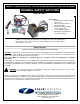
User Guide

2630 Airport Road · Kinston, NC 28504
Phone: 252-522-3031· Fax: 252-522-0214
www.fieldcontrols.com
DRAFT INDUCER KIT WITH PRE-WIRED CONTROL AND
THERMAL SAFETY SWITCHES
Model: DI PAK 24
This draft inducer kit is designed for installation on vent systems serving gas-fired
appliances having a 24V automatic damper and draft hood. The control and thermal
safety switches are pre-wired for easy field installation via the modular damper
control harness connector.
DO NOT DESTROY
THESE INSTRUCTIONS MUST REMAIN WITH EQUIPMENT
CAUTION:
Draft inducers are designed to increase draft in venting applications where inadequate natural draft exists.
This device is NOT designed for sidewall venting applications. The vent to which the inducer is to be mounted is to be
installed in accordance with NFPA 54 or other local codes.
This device MUST be installed by a qualified agency in accordance with the manufacturers installation
instructions.
The definition of a qualified agency is: any individual, firm, corporation or company which either in person or through a
representative is engaged in, and is responsible for, the installation and operation of gas appliances, who is experienced
in such work, familiar with all the precautions required, and has complied with the requirements of the authority having
jurisdiction.
WARNING
: The fan proving pressure switch MUST be adjusted according to the procedure, given in these
instructions, before placing the appliance into service.
Appliances should have a maximum measure flue gas temperature of 750°F at the desired location of the draft inducer.
The installer MUST write or imprint his name, phone number, and date of installation on the tag provided with this device.
The tag MUST be attached to the draft inducer. Recording burner and draft inducer operation information (draft level,
efficiency, etc) is recommended as a guide for future service.
Kit Includes:
• DI-2 Draft Inducer with pre-wired
power cable
• CK-41P control box with pre-
wired power cable
• FTS Thermal Safety Switches,
pre-wired to CK-41P
• 5’ of ¼” Aluminum tubing
• Miscellaneous mounting and
connection hardware