
Cascade Series Install Manual


page 7 of 16
The ideal orientation of unit’s gravity damper is in a level position. If necessary, however, the damper can be in-
stalled at a slight angle. TIP: before beginning the installation, make sure that the fan assembly is undamaged,
and that the fan blade rotates freely. Brace or clamp the fan assembly to a secure object, and temporarily plug
in the fan’s power cord into a grounded power outlet to verify smooth and correct operation.
Be aware that the fan is quite powerful and will draw in loose objects or de
Be aware that the fan is quite powerful and will draw in loose objects or de
bris, and will blow dirt, debris
bris, and will blow dirt, debris
and other objects with force!
and other objects with force!
Use eye protection when operating the fan to avoid injury from blowing sand or debris! Keep hands and
Use eye protection when operating the fan to avoid injury from blowing sand or debris! Keep hands and
other objects away from the rotating fan blade!
other objects away from the rotating fan blade!
TIP: Before beginning the installation, verify that the damper assembly is undamaged, and that the damper doors
operate freely, opening and closing fully without binding or restriction.
INSTALLATION: GRAVITY DAMPER
GRAVITY DAMPER ORIENTATION NOTE
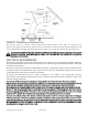
1. From consideration of the principles of whole-house fan
operation, determine the best general area for installation
of the gravity damper assembly. The damper assembly is to
be mounted in the attic with its bottom edge opening into
and ush with the ceiling of the living space. The eggcrate
inlet grille is to be mounted on the ceiling of the living
space, covering and engaging with the opening of the
damper assembly.
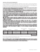
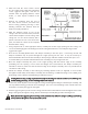
2. Using the cardboard from the fan system’s packaging, or
other suitable material, make a rectangular template for the
rough opening of the damper assembly to these dimensions
(making sure all sides are at right angles to each other):
a. Cascade CA2 and CA3 models: 14-1/4” wide, 22-1/4” long
b. Cascade CA4 and CA5 models: 14-1/4” wide, 30-1/4” long
FIGURE 1 - TEMPLATE
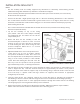
3. Take the template into the attic, above the general area for installation, and determine the exact desired
location for the rough opening for installation of the damper assembly. There must be at least 36” of
vertical clearance above the damper assembly location, and the damper assembly must be fastened to
secure framing (ceiling joist, roof truss, or additional framing) along at least one long side or both short
sides of the damper assembly! Add additional framing as required to support the weight of the damper
assembly and duct.
a. For existing construction, the anges surrounding the opening of the damper assembly may be
removed for clearance (as with 16” on-center framing) and/or to allow the side or sides of the
damper assembly to make direct contact with the framing used to support the damper assembly.
Leave anges in place if they will not be fastened to framing, if possible. Additional framing
may be added after the damper assembly is placed into the rough opening, so the anges can
remain in place if space allows.
b. For new construction, before the ceiling drywall is hung, frame in a rough opening for
installation of the damper assembly from below. Leave the assembly anges in place and
simply attach the damper assembly to the bottom of the framing using appropriate fasteners
installed through the anges. Skip all following steps regarding cutting the rough opening into the
ceiling and proceed with installation of the duct and fan assembly.
P/N 780105001 11/20 Rev A