DRAFT INDUCER INSTALLATION INSTRUCTIONS DO NOT DESTROY: These instructions MUST remain with heating appliance instructions. IMPORTANT! Read all instructions prior to installation and operation of Draft Inducer, CAUTION: DRAFT INDUCERS ARE DESIGNED TO INCREASE DRAFT IN VENTING APPLICATIONS WHERE INADEQUATE NATURAL DRAFT EXISTS.
caution: This draft inducer is to be installed on FUEL OIL, NATURAL GAS or PROPANE burning appliances. This draft inducer is NOT to be installed on solid fuel burning appliances. Refer to unit selection table to determine proper draft inducer selection. caution: Failure to install, maintain, and/or operate the draft inducer in accordance with the manufacturers instructions will result in conditions which may produce bodily injury and/or property damage.
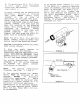
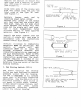
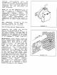
A. If installing a DI-2, DI-3, DI-4, or DI-5, mount draft adjustment plate onto fan housing. {See Figure 1.) B. Draft inducer can be installed on horizontal, vertical or inclined vent pipe. Never install draft inducer on top er side of horizontal or inclined vent pipe. Using supplied mounting template, cut out indicated area on vent pipe. Install inducer into vent pipe and mark the location of the mounting holes. Drill ‘holes to the diameter indicated on template.
¥. A Field barometric draft control should be installed on all oil-fired and gas-fired appliances not equipped with a draft hood. The parametric draft control is used te fine tune the desired draft at the appliance. Some type of draft control device MUST be used on all beating systems with a draft inducer installed. (See Figure 3.) Note: Far gas-fired appliances equipped with draft hood, a parametric draft control is not normally required. (See Figure 4.) G.
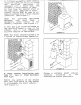
Replace the section of double wall vent pipe with a section of single wall vent pipe of similar length. (See Figure 8.) Crimp both ends of the single wall pipe and insert each end into the inner pipe of the Type "B" vent. (See Figure 7.) Securely fasten each and by inserting sheet metal screws through both layers of the double wall vent pipe and the single wall vent pipe. Sal any air gaps which exist between the double wall vent pipe and the single wall vent pipe.
Venting deficiencies will be automatically sensed by the switch which will prevent heating appliance operation until the vent system is inspected and the deficiency has been corrected. Note: It is the responsibility of the end user to properly maintain the combustion system. The combustion system should be inspected and serviced annually by qualified personnel. Failure to follow such maintenance and inspection procedures may result in generation of toxic carbon monoxide gas.
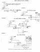
MULTIPLE GAS FIRED SYSTEM DIAGRAM 5 Or CRAFT (FURNACE & WATER HEATER) INDUCER CENTER THERMOSTAT RR-5 RELAY vac OPT. GS-3 SPILLAGE SIP-1 PROVING SWITCH SST A FURNACE WIRING A v pu WATER HEATER WIRING ¥ GAS PRESSURE Endure ers — — ae THERMOS TUPLE f — Te BLOCK GS-3 SPILLAGE SWITCHES INITIAL BURNER AND VENTING SYSTEM OPERATION INFORMATION List operation information for for each heating appliance on the draft induced venting system as a guide for future tune up and service.