ATV Single Row Disc Har row OWNER’S MANUAL WARNING: Read carefully and understand all ASSEMBLY AND OPERATION INSTRUCTIONS before operating. Failure to follow the safety rules and other basic safety precautions may result in serious personal injury.
Thank you very much for choosing this product! For future reference, please complete the owner’s record below: Model: ___ATV-51SGDH________ Purchase Date: _______________ Save the receipt, warranty and these instructions. It is important that you read the entire manual to become familiar with this product before you begin using it. This product is designed for certain applications only. The manufacturer cannot be responsible for issues arising from modification.
WORK AREA • Keep work area clean, free of clutter and well lit. Cluttered and dark work areas can cause accidents. • Keep children and bystanders away while operating a disc. Distractions can cause you to lose control, so visitors should remain at a safe distance from the work area.
ASSEMBLY Step 1: Assemble four Discs to Square Axle Weldment as shown in diagram. Note the direction of the top mounting area of Ref# 12 – support plate. Repeat this step for each gang assembly. 12 12 Step 2: Assemble the Rotating Arm to the Disc Gang Assemblies using U Style Bolts and Nylon Lock Nut M12 as shown in diagram. WAIT to fully tighten lock nuts until later step. Repeat for each disc gang assembly.
Step 3: Install the two Disc Gang Assemblies to the frame using Hex Bolt M12x75 and Nylon Lock Nut M12 as shown in diagram. Step 4: Install the Coupler to the Hitch Tongue using Hex Bolt M12x75, Flat Washer Ø12 and Nylon Lock Nut M12 as shown in the diagram. Note the tabs at center of Hitch Tongue should face upward.
Step 5: Assemble the end of Hitch Tongue to the Frame Assembly using Hex Bolt M12x25, Lock Washer Ø12 and Flat Washer Ø12. Then secure the center of Hitch Tongue to the Frame Assembly using Hex Bolt M12x25 and Nylon Lock Nut M12 as shown in the diagram. Step 6: Adjust the distance between the two Disc Gang Assemblies to 3-4 inches as shown in the diagram. Then tighten all hardware from Step 2.
Step 7: Adjust the angle of two Disc Gang Arms, then secure each side of Gang Arm with Pin and R cotter Pin. Note: the discs should be at an angle when operating. If more angled, the disc will cut into soil more. The Disc is now fully assembled. Disc angles are adjustable for desired harrow/soil preparation. MAINTENANCE • Maintain your disc. It is recommended that the general condition of any disc be examined before it is used.
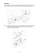
DIAGRAM & PARTS LIST Part# Description Qty Part# Description Qty 1 Frame Weldment 1 12 Disc Support Plate 4 2 Pin 4 13 Long Sleeve 2 3 R Pin 4 14 Disc Pressure Plate 2 4 U Style Bolt 4 15 Hex Bolt M12x75 4 5 Rotating Arm 2 16 Nylon Lock Nut M12 30 6 Hitch Tongue 1 17 Hex Bolt M12x25 3 7 Coupler 1 18 Lock Washer Ø12 1 8 Square Axle Weldment 2 19 Flat Washer Ø12 3 9 Disc 8 20 Round Head Bolt M12x35 16 10 Short Sleeve 8 21 Flat Washer Ø24 2 11
WARRANTY One-year limited warranty TG PO BOX 202 Hopkins, MN 55343 Page 9 of 10
OPTIONAL WHEEL BRACKET: Wheel Bracket Assembly, Please refer to the following diagram For easy towing when not in-use Axle angle must be in STRAIGHT position when using wheel kit.