ATV Disc OWNER’S MANUAL WARNING: Read carefully and understand all ASSEMBLY AND OPERATION INSTRUCTIONS before operating. Failure to follow the safety rules and other basic safety precautions may result in serious personal injury.
Thank you very much for choosing this product! For future reference, please complete the owner’s record below: Model: ___ATV-DH________ Purchase Date: _______________ Save the receipt, warranty and these instructions. It is important that you read the entire manual to become familiar with this product before you begin using it. This machine is designed for certain applications only. The manufacturer cannot be responsible for issues arising from modification.
WORK AREA • Keep work area clean, free of clutter and well lit. Cluttered and dark work areas can cause accidents. • Keep children and bystanders away while operating a disc. Distractions can cause you to lose control, so visitors should remain at a safe distance from the work area.
ASSEMBLY Step 1: Assemble the two disc gang assemblies as shown in diagram. Note: The diagram shows each item number as it is assembled onto the Square Axle Weldment. Tighten Lock Nut so all discs are tight on Square Axle Weldment.
Step 2: Assemble the Hitch Tongue to the Frame using the Hex Bolts, Big Flat Washers and Lock Nuts. Note: Do not over tighten Hex Bolts and Lock Nuts, the Hitch Tongue should rotate up and down freely. Install the Wheel Bracket into the frame as shown in diagram. Note: Check the direction of angle iron on the wheel bracket as shown in diagram.
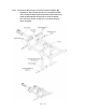
Step 3: Install the two Disc Gang assemblies to the frame using the U bolts and Lock Nuts as shown in diagram. Note: Install the two Disc Gang assemblies in the opposite direction, if they are installed incorrectly the disc will not function properly.
Step 4: Install the Mechanical Screw Jack onto the frame as shown in the diagram using the Hex bolts and Lock Nuts. Note: Do not over tighten these two bolts and Lock Nuts.
Step 5: Install Adjustable Rod to the Hitch Tongue and the Frame using the Hex Bolts and Lock Nuts as Shown. Install the Tires onto the Wheel bracket using the Flat Washers, Hex Bolts and Lock Nuts as shown.
Step 6: There maybe some adjusting of the Hitch Tongue for the height of towing vehicle, this function can be performed by rotating handle on Adjusting Rod. Rotating the handle on the Mechanical Screw Jack will raise the tires up down.
MAINTENANCE • Maintain your disc. It is recommended that the general condition of any disc be examined before it is used. Keep your disc in good repair by adopting a program of conscientious repair and maintenance. If any abnormal vibrations or noise occurs, have the problem corrected before further use. Have necessary repairs made by qualified service personnel.
DIAGRAM & PARTS LIST Page 11of 12
Item No 1 2 3 4 5 6 7 8 9 10 11 12 13 14 15 16 17 18 19 20 Description 2" Coupling Hex Bolt M12×80 Hex Lock Nut M12 Hitch Tongue Adjustable Rod Hex Bolt M16×90 Big Flat Washer Ø16 U style Bolt Nylock Nut M16 End cap Flat Washer Ø12 Handle Grip Hex Bolt M6×30 Handle Nylock Nut M6 Big Flat Washer Ø12 Outside Sleeve Inside Sleeve Hex Bolt M12×60 Frame Qty 1 3 29 1 1 3 6 4 4 7 2 1 1 1 1 1 1 1 1 1 Item No 21 22 23 24 25 26 27 28 29 30 31 32 33 34 35 36 37 38 39 Description Bearing Thick Flat Washer Ø12 Threa