A Sierra Monitor Company Driver Manual (Supplement to the FieldServer Instruction Manual) FS-8700-101 Setra Digital Pressure Gage Model 370 APPLICABILITY & EFFECTIVITY Effective for all systems manufactured after May 1, 2001 Driver Version: 1.
FS-8700-101 Setra Model 370 Digital Pressure Gage Manual Table of Contents TABLE OF CONTENTS 1. 2. SETRA MODEL 370 DIGITAL PRESSURE GAGE DESCRIPTION.................................3 DRIVER SCOPE OF SUPPLY...........................................................................................4 2.1. Supplied by FieldServer Technologies for this driver ...................................................4 2.2. Provided by the Supplier of 3rd Party Equipment ...............................................
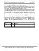
FS-8700-101_Setra Model 370 Digital Pressure Gage Manual 1. Page 3 of 23 Setra Model 370 Digital Pressure Gage Description The ‘Setra Model 370 Digital Pressure Gage’ driver allows the FieldServer to transfer data to and from devices over either RS-232 or RS-485 using the ‘Setra Model 370 Digital Pressure Gage’ protocol. The FieldServer can emulate either a Server or Client. The driver implements a subset of the commands and responses that an actual Setra Model 370 Digital Pressure Gage is capable of.
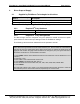
FS-8700-101_Setra Model 370 Digital Pressure Gage Manual 2. Page 4 of 23 Driver Scope of Supply 2.1. Supplied by FieldServer Technologies for this driver FieldServer Technologies PART # FS-8917-01 FS-8700-101 Description Connector, 25 pin male: Connects to DCE, RTS/CTS loop Driver Manual. Provided by the Supplier of 3rd Party Equipment 2.2. 2.2.1. Part # M370 2.2.2.
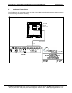
FS-8700-101_Setra Model 370 Digital Pressure Gage Manual 3. Page 5 of 23 Hardware Connections The FieldServer is connected to the rear side of the Model 370 Digital Pressure Gage as shown in the following connection drawing. FieldServer Technologies 1991 Tarob Court Milpitas, California 95035 USA Web:www.fieldServer.com Tel: (408) 262-2299 Fax: (408) 262-9042 Toll_Free: 888-509-1970 email: support@fieldServer.
FS-8700-101_Setra Model 370 Digital Pressure Gage Manual 3.1. Page 6 of 23 Hardware Connection Tips / Hints The following notes are extracted from the Setra 370 Operator Manual. The Setra Digital Pressure Gage implements the majority of the RS-232 communications standard, but does not provide handshaking lines (such as busy, DSR, or DTR). The four lines which must be connected are diagrammed below, along with the pin layout of the female connector on the back of the gage.
FS-8700-101_Setra Model 370 Digital Pressure Gage Manual 4. Page 7 of 23 Configuring the FieldServer as a Setra Model 370 Digital Pressure Gage Client For a detailed discussion on FieldServer configuration, please refer to the FieldServer Configuration Manual. The information that follows describes how to expand upon the factory defaults provided in the configuration files included with the FieldServer (See “.csv” sample files provided with the FieldServer).
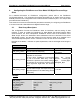
FS-8700-101_Setra Model 370 Digital Pressure Gage Manual 4.2. Page 8 of 23 Client Side Connection Descriptors Section Title Connections Column Title Protocol Function Specify which port the device connected to the FieldServer Specify protocol used Baud* Specify baud rate Parity* Data_Bits* Stop_Bits* Specify parity Specify data bits Specify stop bits Specify hardware handshaking Handshaking* RTS, RTS/CTS, None The Setra Model 370 does not support handshaking.
FS-8700-101_Setra Model 370 Digital Pressure Gage Manual 4.4. Page 9 of 23 Client Side Map Descriptors 4.4.1.
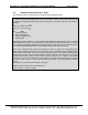
FS-8700-101_Setra Model 370 Digital Pressure Gage Manual 4.4.4. Page 10 of 23 Map Descriptor Example #1 – Read Pressure. In this example a Map Descriptor is defined which controls the task of reading pressure data from the Setra Model 370 Digital Pressure Gage. The task gets performed every 5.0 seconds. When a response is received the data is stored in the Data Array called DA_PRESSURE stating at element zero (the offset).
FS-8700-101_Setra Model 370 Digital Pressure Gage Manual 4.4.5. Page 11 of 23 Map Descriptor Example #2 – Read Status In this example a Map Descriptor is defined which controls the task of reading status data from the Setra Model 370 Digital Pressure Gage. The task gets performed every 5.0 seconds. When a response is received the data is stored in the Data Array called DA_STATUS stating at element zero (the offset).
FS-8700-101_Setra Model 370 Digital Pressure Gage Manual 4.4.6. Page 12 of 23 Map Descriptor Example #3 - Verify. The verification string contains revision and model information about the Gage. In this example a Map Descriptor is defined which controls the task of reading verification data from the Setra Model 370 Digital Pressure Gage. The task gets performed every 5.0 seconds. When a response is received the data is stored in the Data Array called DA_VERIFY stating at element zero (the offset).
FS-8700-101_Setra Model 370 Digital Pressure Gage Manual 5. Page 13 of 23 Configuring the FieldServer as a Setra Model 370 Digital Pressure Gage Server For a detailed discussion on FieldServer configuration, please refer to the FieldServer Configuration Manual. The information that follows describes how to expand upon the factory defaults provided in the configuration files included with the FieldServer.
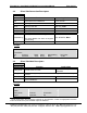
FS-8700-101_Setra Model 370 Digital Pressure Gage Manual 5.2. Page 14 of 23 Server Side Node Descriptors Section Title Nodes Column Title Node_Name Node_ID Protocol Server_Hold_Timeout* Function Legal Values Up to 32 alphanumeric Provide name for node characters This commonly used parameter is not used by this driver and maybe omitted. Specify protocol used Setra370 Specifies time FieldServer will reserve Server side connection while waiting for the Client side >1.
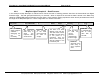
FS-8700-101_Setra Model 370 Digital Pressure Gage Manual 5.3. Page 15 of 23 Server Side Map Descriptors 5.3.1. FieldServer Specific Map Descriptor Parameters Column Title Map_Descriptor_Name Data_Array_Name Data_Array_Offset Function Server_Hold_Timeout* 5.3.2.
FS-8700-101_Setra Model 370 Digital Pressure Gage Manual 5.3.3. Page 16 of 23 Server Map Descriptor Example. This Map Descriptor defines a capability of the FieldServer to respond to a poll for an immediate Pressure Print (Command Code = ‘P’). When the poll is received, the driver inspects 5 consecutive array elements starting at offset 0 in the Data Array named DA_PRESSURE. The contents of the 5 elements are defined in Appendix A.1.1.
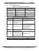
FS-8700-101_Setra Model 370 Digital Pressure Gage Manual Page 17 of 23 Appendix A. Advanced Topics Appendix A.1. How Data Gets Stored Appendix A.1.1. Pressure Data Offset (where x is the offset Notes specified in the MD) X+0 Gage Pressure. A signed real number. Gage Pressure Units. A whole number which is used X+1 as a lookup into the table provide in section “Appendix A.
FS-8700-101_Setra Model 370 Digital Pressure Gage Manual Page 18 of 23 Appendix A.2. Gage Pressure Units The driver does not report status and pressure reading units as text strings. Rather, the driver reports and index number. Use the index number and the table below to determine the units being reported. Index # 0 1 2 3 4 5 6 7 8 9 10 Meaning The Units field could not be interpreted correctly / there were no units reported / the units reported were not part of the following list.
FS-8700-101_Setra Model 370 Digital Pressure Gage Manual Page 19 of 23 Appendix B. Troubleshooting tips Appendix B.1. Connection Tips & Hints The digital pressure Gage must be left in an operational state, in which it is able to respond to the commands (polls) sent by the FieldServer. It is possible to enter a configuration mode using the buttons on the front panel of the Gage and then fail to complete the configuration sequence.
FS-8700-101_Setra Model 370 Digital Pressure Gage Manual Page 20 of 23 Appendix C. Driver Error Messages Message Notes and Corrective Action Set370:#1 FYI. Use an This message is provided for information and may be ignored. Read Array called <%s> to Appendix C.1 for more information. expose diagnostic info. This message is provided for information and may be ignored. The Set370:#2a. FYI.
FS-8700-101_Setra Model 370 Digital Pressure Gage Manual Page 21 of 23 Appendix C.1. Exposing Driver Diagnostic Statistics In addition to the standard FieldServer communication statistics described in Appendix C.2 and in the FieldServer Instruction Manual, this driver can also expose some driver statistics by writing data to a data array. A special Data Array name is required.
FS-8700-101_Setra Model 370 Digital Pressure Gage Manual Page 22 of 23 Appendix C.2.
FS-8700-101_Setra Model 370 Digital Pressure Gage Manual Page 23 of 23 THIS PAGE INTENTIONALLY LEFT BLANK FieldServer Technologies 1991 Tarob Court Milpitas, California 95035 USA Web:www.fieldServer.com Tel: (408) 262-2299 Fax: (408) 262-9042 Toll_Free: 888-509-1970 email: support@fieldServer.