Driver Manual (Supplement to the FieldServer Instruction Manual) FS-8700-39 EST3 ECP APPLICABILITY & EFFECTIVITY Effective for all systems manufactured after September 2008 Driver Version: Document Revision: 1.
FS-8700-39 EST3 Driver Manual Table of Contents TABLE OF CONTENTS 1. EST3 Description.............................................................................................................................. 3 2. Driver Scope of Supply.................................................................................................................... 3 2.1. Supplied By FieldServer Technologies for this Driver .................................................................... 3 rd 2.2.
FS-8700-39 EST3 Driver Manual 1. Page 3 of 21 EST3 Description The EST3 External Communications Protocol (ECP) driver allows the FieldServer to transfer data to and from EST devices over RS-232 or RS-485 (with converter) serial ports using the EST3 ECP protocol. In the EST application the FieldServer always emulates a Client.
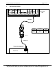
FS-8700-39 EST3 Driver Manual 3. Page 4 of 21 Hardware Connections EST3 ECP TB2 FS-8915-10 Model 8051 Function RX TX GND FROM DB9F/M Pin 2 Pin 3 Pin 5 EST3 ECP TB2 TX 2 RX 2 COM 2 8917-03 8917-03 FS-8915-10 Connect to one of the RS-232 Ports on the FieldServer 8 FieldServer 1 P1 FieldServer Technologies 1991 Tarob Court Milpitas, California 95035 USA Web: www.fieldserver.com Tel: (408) 262 2299 Fax: (408) 262 2269 Toll Free: (888) 509 1970 email: support@fieldserver.
FS-8700-39 EST3 Driver Manual 4. Page 5 of 21 Configuring the FieldServer as a EST3 Client For a detailed discussion on FieldServer configuration, please refer to the FieldServer Configuration Manual. The information that follows describes how to expand upon the factory defaults provided in the configuration files included with the FieldServer (See “.csv” sample files provided with the FieldServer).
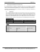
FS-8700-39 EST3 Driver Manual 4.2. Page 6 of 21 Client Side Connection Descriptors Section Title Connections Column Title Function Specify which port the device is connected to the FieldServer Specify baud rate Specify parity Specify data bits Specify protocol to be used by this port Port Baud Parity* Data_Bits* Protocol Legal Values P1-P8, R1-R2 9600, 19200 None 8 EST3 1 2 Example // Client Side Connections Connections Port P8 4.3.
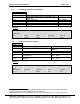
FS-8700-39 EST3 Driver Manual 4.4. Client Side Map Descriptors 4.4.1. FieldServer Related Map Descriptor Parameters Column Title Function Map_Descriptor_Name Name of this Map Descriptor Data_Array_Name Name of Data Array where data is to be stored in the FieldServer Data_Array_Offset Starting location in Data Array Function Function of Client Map Descriptor 4.4.2.
FS-8700-39 EST3 Driver Manual Column Title EST_Alarm_DA* EST_Trouble_DA* EST_Supervisory_DA* EST_Monitor_DA* EST_Others_DA* EST_Active_DA EST_Relay_Conf_DA EST_Types_DA EST_Types_Update DA_Bit_Name EST_Report_Type 4 Page 8 of 21 Function 4 Data Array to store Alarm state Data Array to store Trouble 4 state Data Array to store Supervisory 4 state 4 Data Array to store Monitor state Data Array to store state other than Alarm, Trouble, Supervisory 4 or Monitor Data Array to store the raw value of the ac
Map Descriptor Example 2: ,Function ,Rdbc ,Node_Name ,EST_1 ,EST_Panel ,1 ,EST_Card ,1 Page 9 of 21 ,Address ,0 ,Length ,20 ,Scan_Interval ,5.0s ,Data_Array_Offset ,0 ,Function ,Rdbc ,EST_Trouble_DA ,TROUBLES ,EST_Alarm_DA ,ALARMS ,Node_Name ,EST_1 ,EST_Panel ,1 ,EST_Card ,1 ,Address ,0 FieldServer Technologies 1991 Tarob Court Milpitas, California 95035 USA Web: www.fieldserver.com Tel: (408) 262 2299 Fax: (408) 262 2269 Toll Free: (888) 509 1970 email: support@fieldserver.
FS-8700-39 EST3 Driver Manual Page 10 of 21 Appendix A. Driver Notes Appendix A.1. PanelMasks: The 8 PanelMask parameters combine to form a 64-bit field in which each bit denotes an EST panel in the network. Commands that use the PanelMasks are executed by each panel for which the corresponding bit is set. The Map Descriptor need only define non-zero bytes in the PanelMask. Typically this will be EST_Panel_Mask_1 with a value of 1. Appendix A.2.
Example Configuration using Delta Mode only Page 11 of 21 Baud 9600 ,Scan_Interval ,10.0s ,- Timeout 4s ,Data_Array_Name ,DA_TEST1 ,DA_TEST1 ,Data_Array_Offset ,0 ,20 Data_Array_Length 100 40 40 Protocol, EST3, ,Function ,Rdbc ,Passive_Client ,Node_Name ,Node_A ,Node_A ,EST_Panel ,1 ,7 ,EST_Card ,1 ,3 ,Address ,0 ,130 ,Length ,20 ,20 FieldServer Technologies 1991 Tarob Court Milpitas, California 95035 USA Web: www.fieldserver.
FS-8700-39 EST3 Driver Manual Appendix A.5. Page 12 of 21 Optional Data Arrays When optional parameters (EST_Alarm_DA, EST_Trouble_DA, EST_Supervisory_DA, or EST_Monitor_DA) are used, the driver automatically separates the Alarm Trouble, Supervisory, and Monitor bit from the incoming EST message and places the bit(s) in these Data Arrays at the same offset as the incoming message. Other types can be stored in EST_Others_DA Data Array.
EST_Report_Type Page 13 of 21 ,Data_Array_Name ,DA_Dirtiness ,Data_Array_Offset ,0 ,Function ,Rdbc ,Node_Name ,EST_1 ,EST_Report_Type ,Sensitivity ,EST_Panel ,1 ,EST_Card ,2 ,Address ,1 ,Length ,3 FieldServer Technologies 1991 Tarob Court Milpitas, California 95035 USA Web: www.fieldserver.com Tel: (408) 262 2299 Fax: (408) 262 2269 Toll Free: (888) 509 1970 email: support@fieldserver.com Map_Descriptors Map_Descriptor_Name MD_Poll_Sensitivity ,Scan_interval ,5.
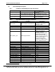
FS-8700-39 EST3 Driver Manual Appendix A.6. Page 14 of 21 Object Types and Required Parameters The tables below list the fields required for the Map Descriptor implementing each object type.
FS-8700-39 EST3 Driver Manual Appendix A.7.
FS-8700-39 EST3 Driver Manual Page 16 of 21 Appendix B. Troubleshooting Tips Appendix B.1. Multiple Com Errors To solve multiple com errors, try adding an IC_Timeout parameter to the Client Side connections and set it to 0.5s. FieldServer Technologies 1991 Tarob Court Milpitas, California 95035 USA Web: www.fieldserver.com Tel: (408) 262 2299 Fax: (408) 262 2269 Toll Free: (888) 509 1970 email: support@fieldserver.
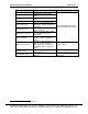
FS-8700-39 EST3 Driver Manual Page 17 of 21 Appendix C. EST3 Data Format: Appendix C.1. Input data format Each input device is associated with a 16-bit value. The contents of the 16 bits are used to generate status types as shown in the table below. Each incoming event is allocated to a status type depending on its device type as shown in the table. It is possible to override this default status type allocation. Refer to Appendix A.5 for more information.
FS-8700-39 EST3 Driver Manual Type TestEvent DeviceCompatabilityFault LogicAnd LogicMatrix ServiceGroup TimeControl GuardPatrol CheckInGroup Internal use only Disabled Internal use only Instruction Text Object Running Audible Visual SupervisedOutput NonSupervisedOutput CommonAlarmPutput CommonTroubleOutput CommonSupervisoryOutPut CommonMonitorOutput LEDOutput AnalogOutput AudioMessage Amplifier Card SecurityAlarm SecurityTrouble SecurityTamper SecurityMaintenance SecurityCommunicationFault SecurityDisarmed
FS-8700-39 EST3 Driver Manual Type AccessReaderFault AccessInternalFault AccessCommunicationFault CmdList Appendix C.2. Page 19 of 21 Encode Value 148 149 150 151 Alarm Trouble Supervisory Monitor Others Y Y Y Y Output data format Each output device is associated with a 16-bit value. This value consists of two byte fields, the device type (LSB) and the device state (MSB).
FS-8700-39 EST3 Driver Manual Page 20 of 21 Appendix D. EST3 ECP Connection Statistics: The EST3 ECP protocol has two distinct levels: • A poll-response connection is maintained by the EST panel acting as the master. The bytes transferred in this process are displayed on the FieldServer as SCADA bytes transmitted and received. • The FieldServer acts as a client by inserting requests into its response messages; the EST panel then inserts the requested data into its subsequent polling messages.
FS-8700-39 EST3 Driver Manual Page 21 of 21 Appendix E. Driver Error Messages Error Message EST3:#01 FYI. For an Old EST3 Panel, Read MD length must be even. EST3:#02 Err. Read MD length must > 0 and <= %d EST3:#03 Err. Write MD must have length = 1 EST3: #04 Unknown Escape Sequence 1B %02X considered as %02X Description and Action Required This message will be displayed once if any Map Descriptor in a configuration file has an odd length.