
User Manual


| NX25-120 & NX25-240 SERIES AC FUEL TRANSFER PUMPS
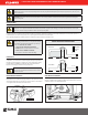
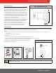
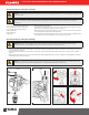
Servicing the Bypass Valve (Dis-assembly)
1. Using needle nose pliers, place the bypass valve retainer on top of the bypass valve spring. Carefully align the slot in the top of the bypass valve retainer with the locking tab
ontop of the bypass valve (Figure 4).
2. Push the bypass valve retainer down over the locking tab on the bypass valve. Push the retainer down (compressing the spring) until it is completely below the locking tab
(Figure5).
3. Rotate the bypass valve retainer 90 degrees counterclockwise and allow the spring to gently push it back up to contact the locking tab. The locking tab MUST be seated in the
indentation in the bypass valve retainer (Figure 6).
WARNING! Always wear eye protection anytime you look into the Pump Outlet; a mispositioned or improperly installed valve spring retainer can pop up
unexpectedly. Note that use of a small flashlight can help you better see and more easily align the components in this task.
WARNING! It is critical that the locking tab be seated in the indentation in the bypass valve retainer as illustrated. Failure to do so can cause the retainer to come
offwhen operating in bypass mode, potentially damaging the pump, or ejecting upward through the pump outlet while servicing.
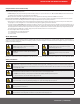
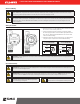
Servicing the Bypass Valve (Re-assembly)
The bypass valve is located inside the pump housing.
Itisaccessed through the inlet and outlet openings.
It consists of three main components (Figure 1):
A. Bypass Valve Retainer
B. Bypass Valve Spring
C. Bypass Valve
1. Unbolt the pump from the tank adapter.
2. Using a blunt object approximately 4" long (i.e. a deep well socket on an extension) inserted in the inlet opening,
push the bypass valve firmly in place against the seat it seals on (Figure 2).
3. While holding the bypass valve firmly in place with the socket, insert needle nose pliers (at least 4" long) into the
outlet opening and grasp the bypass valve retainer (Figure 2 & 3).
4. Push the bypass valve retainer down slightly and rotate it 90 degrees counter‑clockwise. This will align the slot in
the retainer with the key on the valve, allowing you to remove the retainer (Figure 2 & 3).
Figure 1
A
B
C
Figure 3
Figure 5 Figure 6
Figure 4
Figure 2
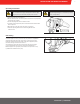
WARNING! Disconnect electrical power and relieve any pressure in the lines prior to servicing this pump! Failure to do so can result in damage to the equipment and
personal injury or death!
IMPORTANT! Removal of the bypass valve in the NX25‑120 or NX25‑240 series pump requires special attention; please adhere to the replacement procedure in the
kit instructions to minimize the possibility of damaging the pump housing during the removal and re‑installation process. Kit instructions are available at
www.fillrite.com.