
Instruction Manual


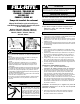


Owner's Operation & Safety Manual
for EXPLOSION-PROOF & RAIN-PROOF
FR1200C / FR2400C DC
FR4200D / FR4400 DC
SD1202 DC / FR600C / SD602 AC
FUEL TRANSFER PUMP
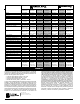
Models FR1205C, FR1210C, FR1211C,
FR2410C, FR2411C, FR4210D, FR4211D,
FR4410, FR4411, FR610C, FR611C,
SD1202, SD602
FR610C (shown)
FR1211C (shown)
SAFETY INSTRUCTIONS
Electrical wiring should be done by a
licensed electrician in compliance with
local, state and national electrical code,
ANSI/NFPA 70, 30, 30A as appropriate.
Rigid conduit should be used and a
proper ground must be provided to avoid
the possibility of electrical shock. Failure
to comply with this warning could result
in serious injury and/or loss of property.
Use only static wire, conductive hose
when pumping flammable fluids.
WARNING
This product should not be used for fluid transfer into aircraft. This
product is not suited for use with fluids for human consumption or
fluids containing water.
To ensure safe and efficient operation, it is essential to read and follow
each of these warnings and precautions.
1. Do NOT smoke near pump or use pump near an open flame.
Fire could result.
2. Disconnect power to pump before servicing pump.
3. Take motors needing service to an authorized repair shop to
maintain “explosion-proof” and “rain-proof” integrity.
4. A Fill-Rite filter should be used on pump outlet to ensure that no
foreign material is transferred to fuel tank.
5. The pump motor is equipped with thermal overload protection.
If overheated, it will shut itself off without any damage to the
windings. Move ON / OFF lever to the ‘OFF’ position to reset
pump.
6. Tank or barrel should be anchored to prevent tipping in both
the full and empty conditions.
7. To minimize static electricity build-up, keep nozzle in contact
with container being filled.
1
The Fill-Rite Series FR1200C, FR2400C, FR4200D, FR4400, FR600C,
SD1202, and SD602 products are positive displacement, rotary vane
pumps. Their rugged motors are explosion-proof and rain-proof to
ensure a long life of dependability.
GENERAL DESCRIPTION
DC PUMPS INSTALLATION INSTRUCTIONS
HEAVY DUTY:
1. Tightly screw suction pipe (1200KTG9099) into inlet flange
(1200F6465) of pumping unit.
2. Extend suction pipe into tank or barrel to within 3" of tank bottom.
Do not rest suction pipe on bottom of tank.
3. Screw inlet flange of pump into tank or barrel opening. Inlet flange
must be completely and securely threaded into an undamaged tank
or barrel bung.
STANDARD DUTY:
1. Secure nozzle boot (1200G8521) to motor endplate with the
two supplied bolts (300F7751) as illustrated on Page 3 of
manual.
2. Tightly screw extension pipe (VP1400F7687) into bung adapter.
Attach suction pipe (VP1400F7686) to extension pipe in the
same manner.
3. Cut suction pipe at a length that will place its end within 3” of the
container bottom. If a longer suction pipe is required, order
additional extension (VP1400F7687).
4. Screw bung/suction pipe assembly securely into container
opening.
HEAVY DUTY AND STANDARD DUTY (Electrical)
1. Install pump. Read and understand all of the electrical wiring
instructions before proceeding.
2. If pump does not have proper grounding, meaning continuous metal
to metal connection from one component to the next, including tank,
bung, pump, meter, filter, hose and nozzle, the pump needs to be
electrically bonded to supply tank or vehicle frame. To electrically
bond pump, remove green bonding screw located next to junction
box cover. Insert this screw through eyelet of furnished green
bonding wire assembly and refasten it securely to the pump. The
other end of the wire is to be stripped of insulation and the bare wire
securely bonded to the vehicle frame or skid tank.
CAUTION: Do not connect the positive or negative power to
the green screw or wire as this could cause a fire.
3. Remove pump’s electrical junction box cover and straighten the 2
wires to make the stripped wire ends accessible outside of the
junction box.
4. Screw furnished cable connector into ½ inch NPT conduit opening
in pump junction box.
5. Strip 6 inches of the outer covering from one end of the furnished
electrical cable being careful not to damage the black and red wire
insulation.
6. Loosen cable connector nut and pass the stripped end of the
furnished cable through the cable connector until 2 inches of the
unstripped cable is within the cable connector. Tighten the cable
connector nut.
7. Strip ½ inch of the installation from the ends of the red and black
cable wires. Using the furnished wire nuts, connect these wires
to the pump wires matching the colors. Be sure no bare wire is
exposed.
8. Fold wires into junction box and replace cover making sure the
gasket is in place. Make sure all screws are seated so there is
no space between the cover and the junction box.
ALL PUMPS
Use Teflon® Tape on all pipe threads.
Do NOT install additional foot valves or check valves that do
not have a pressure relief valve.
DANGER