FILTERSCAN® WiFi Air Filter Monitor Models FS-245-B & FS-245-C Reference Guide Version 4.03 The information contained herein is proprietary and is not to be used for purposes other than as an aid in the operation and/or maintenance of the of the product described herein and is not to be released or reproduced by anyone without the written permission of CleanAlert, LLC.
Table of Contents Introduction ………………..…………………….………………………………………………………… In The Box ..............................…………………………………………………………………………. Tools Required ............…………………………………………………………………………………. Safety ………………….…………………………………………………………………………………. Application ………….……………………………............................................................................. FCC Compliance ……………..………………………………………………………………………….. IC Compliance ………………..…………………………………………………………………………..
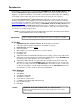
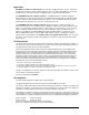
Introduction Congratulations on your purchase of the CleanAlert FILTERSCAN® WiFi Air Filter Monitor. The CleanAlert FILTERSCAN WiFi Air Filter Monitor continuously and automatically monitors the clogging* of an air filter installed into a household or commercial forced air heating, air conditioning, or heat pump system and provides alerts when the filter clogs and needs to be replaced.
Application FILTERSCAN WiFi Air Filter Monitor is an air filter clogging detection system. It has been designed to monitor the change in differential pressure as a result of dirt build up on an air filter and alert the user when the amount of clogging reaches a pre-determined threshold. The FILTERSCAN WiFi Air Filter Monitor is compatible with most air filters ranging in differential pressure drop from 0.10”wg to 4.
Sign Up & Configure AirFilterSentry Notification Service Enter the Serial Number(s) and MAC Address(es) of your FILTERSCAN WiFi unit(s), which is(are) located on the back of the Monitor Housing(s) and on the product box.
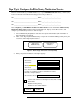
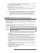
Figure 2: Sign Up Page - Create Login and Password 4. After submitting your profile information on the Sign Up page, you will receive an email with an activation link. Upon clicking on that link your browser will open as seen below. Note: The email entered upon Sign Up must be correct, otherwise you will not receive this confirmation email and will have to start the Sign Up process again. Thank you for verifying your account. Now, just sign in to complete the sign up process.
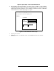
ADD MONITOR *required field *Location *Device Name *Serial # *MAC Address *Device Time Zone Format for Notifications (GMT 5:00) Eastern Time (US & Canada) Email Cell Phone Numbers for Text Notifications Phone Help appears here Phone 1 Phone 2 Phone 3 Email Addresses for Email Notifications Email Help appears here Email 1 Email 2 Email 3 Text/Email Messages Text/Email Message Help appears here Clog Notification Text Location Device Name %SerialNumber% Preview: Battery Low Notification Text Locatio
i. Check the Location and or the Device Name check boxes to automatically add those to the alert messages you select. The “Preview” shows you how the text and or email will appear. j. Check the “Allow automatic updates to your FILTERSCAN software” box if you want to receive automatic software updates. This remote update feature is transparent to you and no action is required after updates are installed. k. Click on Submit. This will send you to the Contact page. 7. Enter Contact Information.
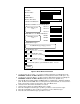
8. Enter Billing information – [NOTE: This will appear differently depending on account types]. ENTER BILLING INFORMATION *required field Same as Contact *First Name *Last Name Company *Email *Address 1 Address 2 *City *Country *State *Province *Zip Code *Phone # Submit Figure 6: Billing Information 9. Click on Submit. 10. Enter credit card information on the payment page. NOTE: This will appear differently depending on payment types. 11.
12. If you have another Monitor to sign up (Home+ and Manager accounts only), Log out and Log in. Select “Monitors” from the Home Page, then select “Add Monitor”. 13. Go to Step 6 to sign up additional monitors. 14. If you need to change any information you’ve entered for any monitor, click on “Edit Monitor” on the Home page. 15. Make the necessary changes and click on Submit. 16.
b. Attach the FILTERSCAN WiFi Air Filter Monitor by aligning its sensor tube with the larger hole and secure the Housing using the mounting screws supplied. The sensor tube does not extend into the duct. 7. For Duct Board plenum installation, follow the directions below. Otherwise go to Step 8. a. Obtain Toggle Bolts (available at Home Depot) (1) #1/8" x 2" SKU 261181 Package of 25 or (2) #1/8" x 3" SKU 261203 Package of 25 b.
8. IMPORTANT! Set the Upstream/Downstream switch shown in Figure 10 so that it matches the FILTERSCAN WiFi Air Filter Monitor’s position with respect to the air filter (that is, OFF for upstream mounting or ON for downstream or differential mounting). Please see the APPENDIX for 'Various HVAC Configurations for Monitor Installation' configurations.
has not yet been calibrated to the air filter and HVAC system upon which it is installed. Additionally, the WiFi Status LED will blink a series of Red and Green. Wait until all blinking has stopped. 5. Go to Section Connect to a Wireless Router. Applying Power – Model FS-245-B (Battery/Adapter) 1. This model is powered from either four AA batteries or an optional wall mount power adapter. If the adapter is installed, the batteries may remain in place or be removed.
Connect to a Wireless Router with a WPS Button 1. Depress the WPS button on your router for two to ten seconds until its WiFi LED begins to blink. See your router user’s manual if you do not know what that button looks like. Timing varies with router manufacturers. 2. Reference Figure 12 to locate the FILTERSCAN WiFi Air Filter Monitor WPS button. 3.
Table 1 WiFi Trouble-shooting Guide Locate the internal WiFi Status Indicator above. (The Heartbeat and other normal, non-WiFi status indications which appear on the STATUS LED are shown elsewhere in this manual.) LED Blink Indication None Flashes Red 1 time, pattern repeats 3 times. Flashes Red 2 times, pattern repeats 3 times. Flashes Red 3 times, pattern repeats 3 times.
4. Using your iPhone or iPad, go to the Settings app and connect to the FILTERSCAN network. It may take a few minutes for the FILTERSCAN network to appear. 5. Once the iPhone or iPad is connected to the FILTERSCAN network, open a web browser. 6. Enter the IP address 192.168.1.1 in the URL box Loading Pre-scanned Networks Figure 13: FILTERSCAN WiFi Network Configuration Page 7. Wait for the page to update and show the available networks. This may take several minutes.
For WEP networks, the security key entered is the hexadecimal key, not the passphrase used to generate the key. WEP128 keys must be 26 digits long consisting of characters 0-9 and A-F. Manual pairing using an Android smartphone or tablet 1. Items needed: a. A smartphone or tablet with WiFi running Android 6.0 (“Marshmallow”) or later. b. The wireless password or passphrase for your router.
The FILTERSCAN WiFi Air Filter Monitor does not support # $ and & (See acceptable Special Character chart in FAQ section) in the SSID (NETWORK NAME) or in WPA or WPA2 passphrases. 17. Your FILTERSCAN WiFi Air Filter Monitor is now connected to your wireless router, and has initiated a connection process where the FILTERSCAN WiFi Air Filter Monitor and your wireless router communicate with each other and establish a connection with no further action needed.
Calibrating the FILTERSCAN WiFi Air Filter Monitor Figure 15: Front cover of the FILTERSCAN WiFi monitor Important: If you are not going to calibrate your monitor immediately after installing your monitor, REMOVE one of the batteries. When ready to calibrate after initial installation, reinstall battery. Install a clean, new air filter into your heating and cooling system. Press and immediately release the SEND button to see if Calibration has already been started or done.
The SERVICE FILTER control is a fine tuning adjustment that has been calibrated during production to the mid-range, which is the Recommended Setting. This control allows the user to change the point at which the clog alarm will be triggered. Turning the SERVICE FILTER adjustment knob clockwise will cause the FILTERSCAN WiFi Air Filter Monitor to issue an alarm at a lower level of filter clogging (less energy consumption).
NOTE: A new or cleaned air filter should always be installed whenever the CALIBRATE operation is performed. Low Battery When the FILTERSCAN WiFi Air Filter Monitor detects a low battery condition, an alert condition is triggered. The STATUS LED will blink yellow approximately once per minute to indicate a low battery in the Monitor. Replacing the Monitor batteries (see APPENDIX) will reset the alert condition.
b. IF YOU PRESS RESET BY MISTAKE, press it again for 2 seconds until the Status LED blinks Amber and a beep is heard. 3. Wait at least one minute before turning your HVAC system ON – The FILTERSCAN WiFi Air Filter Monitor is starting the automatic calibration process during this time, calibrating itself to the air filter and HVAC system into which it is installed. 4.
on the system’s pressure when one or two registers are changed and therefore the less effect on when the clog alert will occur. Regular changes to system registers could make the performance unpredictable. What if my FILTERSCAN WiFi Air Filter Monitor stops sending status data? What if the Status report at my AirFilterSentry Notification Service account does not display a recent update Date? There could be many causes for data to not reach the AFS server. 1.
There is a conduit connector knock-out located on the lower side of the monitor housing. What voltage is acceptable to power the FILTERSCAN WiFi Air Filter Monitor via the conduit? Typically 24V AC/DC, although an input voltage as low as 15V DC is acceptable. Model FS-245-B Do I have to install batteries if I power the Monitor from the optional AC Adapter? No. Can I utilize both the AC Adapter and batteries for backup? Yes, you can install batteries even though you also have an AC adapter installed.
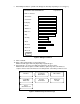
) * + , . / : ; < = > ? @ [ \ ] ^ _ ` { | } ~ Yes Yes Yes Yes Yes Yes Yes Yes Yes Yes Yes Yes Yes Yes Yes Yes Yes Yes Yes Yes Yes Yes Yes Yes Yes Yes Yes Yes Yes Yes Yes Yes Yes Yes Yes Yes Yes Yes Yes Yes Yes Yes Yes Yes Yes Yes Yes Yes How far can the FILTERSCAN WiFi Air Filter Monitor be mounted from the wireless router? The range of the WiFi signal is similar to the range of your wireless devices (laptop, smartphone, etc.).
Relay Output Text & E-Mail Notification**: Indicators: Electrical Connections: Mounting Monitor Dimensions WiFi Module WiFi Authentication Transmission Range FCC Identification # Industry Canada # Optional one form C dry contact @ 500 mA max – Model FS-245-C User configurable SMS text messaging and e-mail Green / Yellow / Red Status LED and audible beeper Power - 2.
The FILTERSCAN WiFi Air Filter Monitor has the ability to allow the AirFilterSentry Notification Service to update the Monitor software.
Cloud Server................. The computer server on which the AirFilterSentry Notification Service resides and operates. The hosting service ensures database backups and redundancy to provide maximum up-time of their systems. MAC Address ............... Media Access Control unique identifier assigned to the WiFi radio within the FILTERSCAN WiFi Air Filter Monitor. Indicators Green STATUS LED...... The blinking Green STATUS LED at the FILTERSCAN WiFi Air Filter Monitor indicates normal operation.
Various HVAC Configurations for Monitor Installation Figure 16: Installation on HVAC systems with vertical return and supply ducts Figure 17: Installation on HVAC systems with horizontal return and vertical supply ducts 28
Figure 18: Installation on HVAC systems with horizontal return and supply ducts Figure 19: Installation on HVAC systems with wall or ceiling-mounted air filters 29
Figure 20: Installation of the optional CA-4DP Tubing Kit mounted differentially across the filter.
Optional Dry Contact Relay Output Operation 1. When connecting the relay output to an external building automation system (BAS) or alarm, it is recommended that the Common and Normally Closed contacts be used. This allows the external system or alarm to detect when the cabling is cut. 2. During a clog alarm, the relay will activate for one second, opening the Normally Closed contacts, and closing the Normally Open contacts. 3.