
Data Sheet


9
I
Auxiliary output
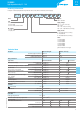
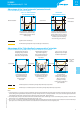
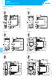
A solid state output at terminals Y1-Y2 is provided (rated 12VDC, 80mA/1W max.): this can be used with the power
module 19.91.9.012.4000 connected by the dedicated 011.19 connector. Or, it is possible to connect a suitable relay
(for example, 38-48-49-4C-58-59 interface module) provided the coil is within the rating, and the wiring does not
exceed 40cm length. The auxiliary output is driven exclusively by the light sensor of the device, and is consequently
independent of the time switch. With the main contact, this permits a flexible lighting system controlled by the ambient
light, both with and without the influence of the time switch function.
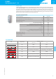
19.91 power module specification
Contact configuration 1 CO (SPDT)
Rated current/Maximum peak current (I
N
/I
max
) A 16/30 (120A – 5ms)
Rated voltage/Maximum switching voltage (U
N
/U
max
) VAC 250/400
Rated load AC15 (230VAC) VA 750
Nominal lamp rating:
230V incandescent/halogen W 2000
fluorescent tubes with electronic ballast W 1000
fluorescent tubes with electromechanical ballast W 750
CFL W 400
230V LED W 400
LV halogen or LED with electronic ballast W 400
LV halogen or LED with electromechanical ballast W 800
Nominal supply voltage (U
N
) VDC 12
Ambient temperature range °C –20…+50
Protection category IP 20
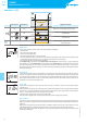
11.31/41/42
LED Supply voltage
NO output contact
11.41/11.42 11.31
OFF Open Open
ON Open Open
ON Open (timing to close in progress) Open (timing to close in progress)
ON Closed Closed
ON Closed (timing to open in progress) Closed (timing to open in progress)
ON Fixed position (On or Off on selector) —
II-2018,www.findernet.com
11
SERIES
11 SERIES
Light dependent relays 12 - 16A