
Data Sheet


X-2017, www.findernet.com
B
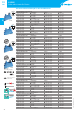
Technical data - 1 & 2 Pole Electromechanical Relays
Insulation
Insulation according to EN61810-1 insulation rated voltage V 250 400
rated impulse withstand voltage kV 4 4
pollution degree 3 2
overvoltage category III III
Insulation between coil and contacts (1.2/50µs) kV 6 (8mm)
Dielectric strength between open contacts VAC 1000
Conducted disturbance immunity
Burst (5…50)ns, 5kHz, on A1 - A2 according to EN61000-4-4 level 4 (4kV)
Surge (1.2/50µs) on A1 - A2 (differential mode) according to EN61000-4-5 level 3 (2kV)
Other data 1 Pole 6A 1 Pole 16A - 2 Pole 8A
Bounce time: NO/NC ms 1/6 2/5
Vibration resistance (10…55)Hz: NO/NC g 10/5 15/2
Power lost to the environment without contact current W 0.2 (12V) - 0.9 (240V) 0.5 (24V) - 0.9 (240V)
with rated current W 0.5 (12V) - 1.5 (240V) 1.3 (24V) - 1.7 (240V)
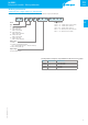
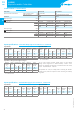
Terminals 38.21 / 38.51 38.61
Wire strip length mm 10 10
Screw torque Nm 0.5 —
Max. wire size solid cable stranded cable solid cable stranded cable
mm
2
1x2.5 / 2x1.5 1x2.5 / 2x1.5 1x2.5 1x2.5
AWG 1x14 / 2x16 1x14 / 2x16 1x14 1x14
38.01 / 38.52 38.11 / 38.62
Wire strip length mm 10 10
Screw torque Nm 0.5 —
Max. wire size solid cable stranded cable solid cable stranded cable
mm
2
1x2.5 / 2x1.5 1x2.5 / 2x1.5 1x2.5 1x2.5
AWG 1x14 / 2x16 1x14 / 2x16 1x14 1x14
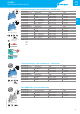
Contact specification - 1 & 2 Pole Electromagnetic Relays
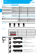
F 38 - Electrical life (AC) v contact current, 1 Pole 6A H 38 - Maximum DC1 breaking capacity, 1 Pole 6A
Cycles
Resistive load - cosϕ = 1
Inductive load - cosϕ = 0.4
DC voltage (V)
DC breaking current (A)
F 38 - Electrical life (AC) v contact current, 1 Pole 16A and 2 Pole 8A H 38 - Maximum DC1 breaking capacity, 1 Pole 16A and 2 Pole 8A
Cycles
Resistive load - cosϕ = 1
Inductive load - cosϕ = 0.4
Resistive load - cosϕ = 1
Inductive load - cosϕ = 0.4
DC voltage (V)
DC breaking current (A)
2 contacts in series
single contact
38.01/11 limit current
38.52/62 limit current
: 2 Pole 8A
: 1 Pole 16A
• When switching a resistive load (DC1) having voltage and current
values under the curve, an electrical life of ≥60·10
3
(1Pole) or
≥80·10
3
(2Pole) can be expected.
• In the case of DC13 loads, the connection of a diode in parallel with the
load will permit a similar electrical life as for a DC1 load.
Note: the release time for the load will be increased.
8
38 SERIES
Relay interface modules - Technical data
38
SERIES