
Datasheet
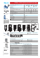
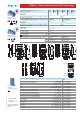

55.12 55.13 55.14
2 CO (DPDT) 3 CO (3PDT) 4 CO (4PDT)
10/20 10/20 7/15
250/400 250/400 250/250
2,500 2,500 1,750
500 500 350
0.37 0.37 0.125
10/0.25/0.12 10/0.25/0.12 7/0.25/0.12
300 (5/5) 300 (5/5) 300 (5/5)
AgNi AgNi AgNi
6 - 12 - 24 - 48 - 60 - 110 - 120 - 230 - 240
6 - 12 - 24 - 48 - 60 - 110 -125 - 220
1.5/1 1.5/1 1.5/1
(0.8…1.1)U
N
(0.8…1.1)U
N
(0.8…1.1)U
N
(0.8…1.1)U
N
(0.8…1.1)U
N
(0.8…1.1)U
N
0.8 U
N
/0.5 U
N
0.8 U
N
/0.5 U
N
0.8 U
N
/0.5 U
N
0.2 U
N
/0.1 U
N
0.2 U
N
/0.1 U
N
0.2 U
N
/0.1 U
N
20 · 10
6
/50 · 10
6
20 · 10
6
/50 · 10
6
20 · 10
6
/50 · 10
6
200 · 10
3
200 · 10
3
150 · 10
3
10/5 10/5 11/3
44 4
1,000 1,000 1,000
–40…+85 –40…+85 –40…+85
RT I RT I RT I
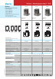
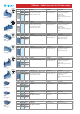
• 3 pole, 10 A
• PCB mount
• 4 pole, 7 A
• PCB mount
Contact specification
Contact configuration
Rated current/Maximum peak current A
Rated voltage/Maximum switching voltage V AC
Rated load AC1 VA
Rated load AC15 (230 V AC) VA
Single phase motor rating (230 V AC) kW
Breaking capacity DC1: 30/110/220V A
Minimum switching load mW (V/mA)
Standard contact material
Coil specification
Nominal voltage (U
N
) V AC (50/60 Hz)
V DC
Rated power AC/DC VA (50 Hz)/W
Operating range AC
DC
Holding voltage AC/DC
Must drop-out voltage AC/DC
Technical data
Mechanical life AC/DC cycles
Electrical life at rated load AC1 cycles
Operate/release time ms
Insulation between coil and contacts (1.2/50
µ
s)
kV
Dielectric strength between open contacts V AC
Ambient temperature range °C
Environmental protection
Approvals (according to type)
1
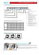
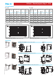
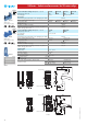
Copper side view Copper side view Copper side view
Features
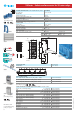
Printed circuit mount, general purpose
2, 3 & 4 Pole relays
55.12 - 2 Pole 10 A
55.13 - 3 Pole 10 A
55.14 - 4 Pole 7 A
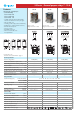
• AC coils & DC coils
• Cadmium Free contacts (preferred version)
• Contact material options
• RT III (wash tight) option available
• 2 pole, 10 A
• PCB mount
FOR UL RATINGS SEE:
“General technical information” page V
55.12 55.13 55.14
55 Series - General purpose relays 7 - 10 A
II-2013, www.findernet.com