
Datasheet

4
Contact specification
Technical data
55 Series - General purpose relays 7 - 10 A
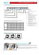
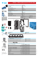
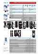
F 55 - Electrical life (AC) v contact current
2 and 3 pole relays
Cycles
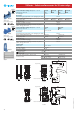
DC voltage (V)
DC breaking current (A)
H 55 - Maximum DC1 breaking capacity
• When switching a resistive load (DC1) having voltage and current
values under the curve, an electrical life of ≥ 100·10
3
can be expected.
• In the case of DC13 loads, the connection of a diode in parallel with
the load will permit a similar electrical life as for a DC1 load.
Note: the release time for the load will be increased.
F 55 - Electrical life (AC) v contact current
4 pole relay
Cycles
contacts in series
2 & 3 pole current limit
4 pole current limit
Resistive load - cosϕ = 1
Inductive load - cosϕ = 0.4
Resistive load - cosϕ = 1
Inductive load - cosϕ = 0.4
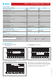
Insulation according to EN 61810-1 2 pole - 3 pole 4 pole
Nominal voltage of supply system V AC 230/400 230
Rated insulation voltage V AC 400 250
Pollution degree 2 2
Insulation between coil and contact set
Type of Insulation Basic Basic
Overvoltage category III III
Rated impulse voltage kV (1.2/50 µs) 4 4
Dielectric strength V AC 2,000 2,000
Insulation between adjacent contacts
Type of insulation Basic Basic
Overvoltage category III II
Rated impulse voltage kV (1.2/50 µs) 4 2.5
Dielectric strength V AC 2,000 2,000
Insulation between open contacts
Type of disconnection Micro-disconnection Micro-disconnection
Dielectric strength V AC/kV (1.2/50 µs) 1,000/1.5 1,000/1.5
Conducted disturbance immunity
Burst (5...50)ns, 5 kHz, on A1 - A2 EN 61000-4-4 level 4 (4 kV)
Surge (1.2/50 µs) on A1 - A2 (differential mode) EN 61000-4-5 level 4 (4 kV)
Other data
Bounce time: NO/NC ms 1/3
Vibration resistance (5…55)Hz: NO/NC g 15/15
Shock resistance g 16
Power lost to the environment without contact current W 1
with rated current W 3 (2 pole) 4 (3 pole) 3 (4 pole)
Recommended distance between relays mounted on PCB mm ≥ 5
II-2013, www.findernet.com