
Datasheet


1
II-2014, www.findernet.com
Features
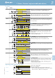
13.81 - Electronic step relay - Rail mount - 1 Pole
13.91 - Electronic step relay and timing step relay
Switch box mount - 1 Pole
• Fixed time (10 minutes) timing function
selectable (13.91)
• Use with 3 or 4 wire connection, with automatic
recognition by the relay
• Control input can be continuously applied
• Longer mechanical and electrical life, and much
quieter than electromechanical step relays
• “Zero crossing” load switching
• Can be mounted behind blanking plates, as
widely used in residential wiring systems such
as; BTicino: Axolute, Matix, Living and Magic,
Gewiss: GW24, Vimar: Plana and Idea ... (13.91)
• 35 mm rail (EN 60715) mount (13.81)
• Cadmium free contact material
13.81 13.91
1 NO (SPST-NO) 1 NO (SPST-NO)
16/30 (120 A - 5 ms) 10/20 (80 A - 5 ms)
230/— 230/—
3,700 2,300
750 450
3,000 1,000
1,500 500
1,000 350
600 300
600 300
600 300
1,500 500
1,000 (10/10) 1,000 (10/10)
AgSnO
2
AgSnO
2
230 230
——
3/1.2 2/1
(0.8…1.1)U
N
(0.8…1.1)U
N
——
100 · 10
3
100 · 10
3
continuous continuous
1,000 1,000
——
–10…+60 –10…+50
IP 20 IP 20
Contact specification
Contact configuration
Rated current/Maximum peak current A
Rated voltage/Maximum switching voltage V AC
Rated load AC1 VA
Rated load AC15 (230 V AC) VA
Nominal lamp rating: 230V incandescent/halogen
W
fluorescent tubes with electronic ballast W
fluorescent tubes with electromechanical ballast
W
CFL W
230V LED W
LV halogen or LED with electronic ballast W
LV halogen or LED with electromechanical ballast W
Minimum switching load mW (V/mA)
Standard contact material
Supply specification
Nominal voltage (U
N
) V AC (50/60 Hz)
V DC
Rated power V A (50 Hz)/W
Operating range AC (50 Hz)
DC
Technical data
Electrical life at rated load in AC1 cycles
Maximum impulse duration
Dielectric strength between: open contacts V AC
supply - contacts V AC
Ambient temperature range °C
Protection category
Approvals (according to type)
• 1 NO (SPST-NO)
• 35 mm rail (EN 60715) mount
• 17.5 mm wide
• 1 NO (SPST-NO)
• Step relay and timing step
relay (10 minutes)
• For mounting within
residential switch boxes
For outline drawing see page 9
13.81/91
Screw terminal
13 Series - Electronic step relays 10 - 16 A
13
SERIES
K