
Data Sheet


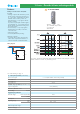


19 Series - Override & Status indicating modules
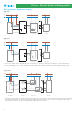
Wiring diagrams - Application examples
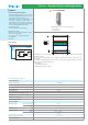
Type 19.21
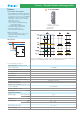
Type 19.31
Controller, PLC
Type 19.21
End - Process ... or ... Sub-system
S
B1
A3
A2
A1
B2
12
11
14
12
11
14
24V AC/DC
Controller, PLC
Type 19.31
End - Process ... or ... Sub-system
S
A3
A2
12
11
14
*
24V AC/DC
12
11
14
* S can be, for example, a NO-contact with the purpose of indicating “in operation” (selecting green as LED color) or a NC-contact with the
purpose of indicating “error” or “alarm” (selecting red or blue as LED color). The LED color has to be chosen through the back side selector.
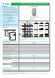
Type 19.32
Controller, PLC
Type 19.32
End - Process ... or ... Sub-system
S1
A4
LED
A3
S2
A2
11
21
24
14
**
24V AC/DC
**
11
21
24
14
* S1 (related to LED 1 and NO 11-14) and S2 (related to LED 2 and NO 21-24) can be, for example, NO-contacts with the purpose of indicating
“in operation” (selecting green as LED color) or NC-contacts with the purpose of indicating “error” or “alarm” (selecting red or blue as LED
color). The LED colors have to be chosen, independently, through the back side selectors.
9