
Data Sheet


2 NO (SPST-NO) separate output
1/3 A
125/250 V AC
125 VA
25 VA
—
1/0.3/— A
10 mW (0.1 V/1 mA)
AgNi + Au
24 V
24 V
0.8 VA (50 Hz)/0.5 W
(0.8...1.1) U
N
(0.8...1.1) U
N
1,000
–20…+50 °C
IP 20
Output specification
Contact configuration
Rated current/Maximum peak current I
N
/I
max
Rated voltage/Maximum switching voltage U
N
/U
max
Rated load AC1
Rated load AC15
Single phase motor rating (230 V AC)
Breaking capacity DC1 (24/110/220 V)
Minimum switching load
Standard contact material
Input specification
Nominal voltage U
N
AC (50/60 Hz)
U
N
DC
Rated power P
N
Operating range V AC
V DC
Ambient temperature range
Protection category
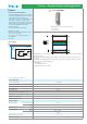
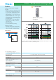
19 Series - Override & Status indicating modules
Features
2-channel status indicating module
• 2-channel indicating module to provide visual
indication of BMS/DDC/PLC input or output
status with immediate indication of its
importance or urgency according to the colour
of the LED. Two NO output contacts, following
the inputs to the module, provide for further
control or status feedback. Commonly used in
building management systems
• 24V AC/DC inputs
• 35 mm rail (EN 60715) mounting
Application examples:
• status reports of heating installations, pumps,
blowers or motor groups
• error reports such as danger of frost or
blocked filter
• fire alarm
• LED indicator, 3 colours: Red, Green ,Blue
• 2 NO control
• 17.5 mm wide
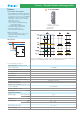
19.32.0.024.0000
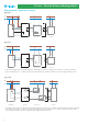
Wiring diagram
The LED colour is selected by the dip-switch on the rear face of the module, prior to mounting
on the 35 mm rail.
The colour is determined by the system designer according to the urgency or importance of
the signal.
Commonly, the following levels of importance or urgency are assigned to the Red, Green and
Blue colours according to EN 60073:
- Red LED: Error
- Green LED: In operation
- Blue LED: Alarm (fire or similar)
3
For outline drawing see page 11