
Data Sheet


4
1 CO (SPDT)
5/15 A
250/400 V AC
1,250 VA
250 VA
0.185 kW
3/0.35/0.2 A
500 mW (10 V/5 mA)
AgCdO
1 NO (SPST-NO)
100 mA/10 mA
24 V
24 V
24 V
1 VA (50 Hz)/0.6 W
(0.8…1.1) U
N
(0.8…1.1) U
N
–20…+50 °C
IP20
Output specification (terminals 12-11-14)
Contact configuration
Rated current/Maximum peak current I
N
/I
max
Rated voltage/Maximum switching voltage U
N
/U
max
Rated load AC1
Rated load AC15
Single phase motor rating (230 V AC)
Breaking capacity DC1 (24/110/220 V)
Minimum switching load
Standard contact material
Feedback output specification (terminals 51-52)
Contact configuration
Maximum / Minimum current
Rated voltage AC/DC
Supply & Input specification
Nominal voltage U
N
AC (50/60 Hz)
U
N
DC
Rated power P
N
Operating range V AC
V DC
Ambient temperature range
Protection category
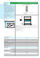
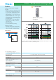
19 Series - Override & Status indicating modules
Features
Override module - Auto/Off/Hand
• Auto/Off/Hand override module intended to
permit the automatic control of pumps, blowers
or motor groups. Or, in the case of installation,
maintenance or failure, to permit the load
equipment to be turned “Off“ or controlled
under “Hand“ control
• 3 function selector switch:
- Auto: work as a monostable relay relay
(following A3 input)
- Off: relay output permanently Off
- Hand: relay output permanently On
• 24V AC/DC supply & input
• 35 mm rail (EN 60715) mounting
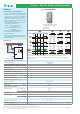
Application examples:
• control of pumps, blowers or motor groups
commonly associated with building
management systems
• 1 CO output contact
• 1 feedback output contact
• 17.5 mm wide
• LED indicator
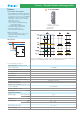
19.41.0.024.0000
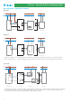
Wiring diagram
In position “H” (Hand) or “O” (Off), a yellow LED will flash and the feedback output (51-52)
will open, to indicate that the module is not in “A” (Automatic) position.
For outline drawing see page 11