
Data Sheet


6
0…10 V (Imax 20mA - short-circuit protected)
>2.5 V
> 5 V
>7.5 V
1 NO (SPST-NO)
100 mA/10 mA
24 V
24 V
24 V
0.9 VA (50 Hz)/0.7 W
(0.8…1.1) U
N
(0.8…1.1) U
N
–20…+50 °C
IP20
(0…10)V Signal specification (terminal Y-in)
Input control signal
Green LED 25%
Green LED 50%
Green LED 75%
Feedback output specification (terminals 51-52)
Output configuration
Maximum / Minimum current
Rated voltage AC/DC
Supply & Input specification
Nominal voltage U
N
AC (50/60 Hz)
U
N
DC
Rated power P
N
Operating range V AC
V DC
Ambient temperature range
Protection category
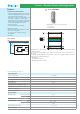
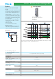
19 Series - Override & Status indicating modules
Features
Analogue override module - Auto/Hand
(0…10)V
• Analogue output module intended to provide,
by the selection switch on the front panel, a
(0…10) V output, automatically or by hand.
With the selector switch in position “A“
(Automatic) the (0…10) V signal is derived
from the controller.
In position “H” (Hand) the controller signal is
ignored and the (0…10) V signal is derived
directly from the potentiometer setting on the
facia of the module
• The level of the (0…10) V output signal is
displayed by 3 green LEDs, set at >25%,
>50% and >75%.
• 24V AC/DC supply
• 35 mm rail (EN 60715) mounting
Application examples:
• permits the direct control of proportional
valves under exceptional circumstances or
where the automatic controller has failed
• Analogue output (0…10)V,
plus 1 feedback output contact
• 17.5 mm wide
• LED indicator
19.50.0.024.0000
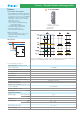
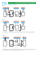
Wiring diagram
In position “H” (Hand) a Yellow LED will flash and the feedback contact will open to indicate
that the module is not in the “A” (Automatic) position.
Y-in
Y-out
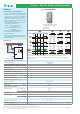
For outline drawing see page 11