
Datasheet


Example: 20 series relay, 35 mm rail (EN 60715) mount, double phase switch, 2 NO (DPST-NO) 16 A contacts, coil rated at 12 V DC,
AgSnO
2
contacts.
2
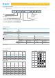
Ordering information
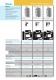
20.22
20.21
20.23
20.24
20.28
43
2
1
2
4
4
20.26
3
2
2
Type
Number
of steps
Sequence
Coil specifications
Nominal Coil code Operating range Resistance
Consumption
voltage
I at U
N
U
N
U
min
U
max
R
(50 Hz)
VVVΩ mA
8 8.008 6.8 8.8 4 800
12 8.012 10.2 13.2 7.5 550
24 8.024 20.4 26.4 27 275
48 8.048 40.8 52.8 106 150
110 8.110 93.5 121 590 64
120 8.120 102 132 680 54
230 8.230 196 253 2,500 28
240 8.240 204 264 2,700 27.5
AC version data
Contact material
0 = AgNi standard
4 = AgSnO
2
Coil voltage
See coil specifications
Coil version
8 = AC (50/60 Hz)
9 = DC
Series
Type
2 = 35 mm rail (EN 60715) mount
No. of poles
1 = Single phase switch 1 NO (SPST-NO)
2 = Double phase switch 2 NO (DPST-NO)
3 = Double phase switch 1 NC+1 NO (SPST-NO+SPST-NC)
4 = 4 sequence double phase switch 2 NO (DPST-NO)
6 = 3 sequence double phase switch 2 NO (DPST-NO)
8 = 4 sequence double phase switch 2 NO (DPST-NO)
2 2 4 09 0 0
... .
01220
20 Series - Modular step relays 16 A
Nominal Coil code Operating range Resistance
Consumption
voltage
I at U
N
U
N
U
min
U
max
R
VVVΩ mA
12 9.012 10.8 13.2 27 440
24 9.024 21.6 26.4 105 230
48 9.048 43.2 52.8 440 110
110 9.110 99 121 2,330 47
DC version data
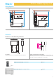
If the coil is operated for a prolonged period of time, adaquate ventilation of the relays must be provided - suggested gap of 9 mm between
adjacent relays.
Technical data
Insulation
Dielectric strength
between supply and contacts V AC 3,500
between open contacts V AC 2,000
between adjacent contacts V AC 2,000
Other data
Power lost to the environment
with rated current and coil deenergised W 1.3 (20.21, 20.23, 20.28) 2.6 (20.22, 20.24, 20.26)
Screw torque Nm 0.8 0.8
Coil terminals Contact terminals
Max. wire size solid cable stranded cable solid cable stranded cable
mm
2
1x4 / 2x2.5 1x2.5 / 2x2.5 1x6 / 2x4 1x4 / 2x2.5
AWG 1x12 / 2x14 1x14 / 2x14 1x10 / 2x12 1x12 / 2x14