
Datasheet


A
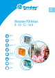
Power relays 1 and 2 pole for direct PCB or
socket mount
Type 40.31/51
- 1 CO 10A (3.5mm pin pitch)
- 1 CO 10A (5.0mm pin pitch)
Type 40.52
- 2 CO 8A (5.0mm pin pitch)
Type 40.61
- 1 CO 16 A (5.0mm pin pitch)
• AC or DC coils according to type
• Cadmium-free contact material
• 8 mm Creepage and Clearance, 6 kV (1.2/50µs)
between coil and contact
• Meets EN 60335-1 glow wire requirements
• 95 series sockets for PCB or 35 mm rail
mounting (EN 60715) with Screw, Screwless or
Push-in terminals
• Coil Indication and EMC suppression modules
99 series and Timer module 86.30 options
• Environmental protection:
RT II - flux proof (Standard)
RT III - wash tight (Option)
* With the AgSnO
2
material the
maximum peak
current is 120A- 5ms on normally open
contact.
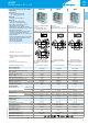
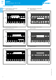
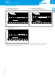
40.31/51 40.52 40.61
• 1 CO 10 A
• 3.5mm pin pitch (40.31),
5.0mm pin pitch (40.51)
• PCB or 95 Series socket mount
• 2 CO 8 A
• 5.0mm pin pitch
• PCB or 95 Series socket mount
• 1 CO 16 A
• 5.0mm pin pitch
• PCB or 95 Series socket mount
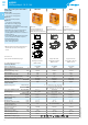
40.31
40.51
Copper side view
Pin length 5.3mm for
PCB or sockets
Copper side view
Pin length 5.3mm for
PCB or sockets
Copper side view
Pin length 5.3mm for
PCB or sockets
For UL ratings see:
“General technical information” page V
For outline drawing see page 12
Contact specification
Contact configuration 1 CO (SPDT) 2 CO (DPDT) 1 CO (SPDT)
Rated current/Maximum peak current A 10/20 8/15 16/30*
Rated voltage/
Maximum switching voltage VAC 250/400 250/400 250/400
Rated load AC1 VA 2500 2000 4000
Rated load AC15 (230VAC) VA 500 400 750
Single phase motor rating (230VAC) kW 0.37 0.3 0.55
Breaking capacity DC1: 30/110/220V A 10/0.3/0.12 8/0.3/0.12 16/0.3/0.12
Minimum switching load mW (V/mA) 300 (5/5) 300 (5/5) 500 (10/5)
Standard contact material AgNi AgNi AgCdO
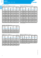
Coil specification
Nominal voltage (U
N
) VAC (50/60Hz) 6 - 12 - 24 - 48 - 60 - 110 - 120 - 230 - 240
VDC —
5 - 6 - 7 - 9 - 12 - 14 - 18 - 21 - 24 -
28 - 36 - 48 - 60 - 90 - 110 - 125
—
Rated power AC/DC/sens. DC VA (50Hz)/W/W 1.2/—/— 1.2/0.65/0.5 1.2/—/—
Operating range AC (0.8…1.1)U
N
(0.8…1.1)U
N
(0.8…1.1)U
N
DC/sens. DC — (0.73…1.5)U
N
/(0.73…1.5)U
N
—
Holding voltage AC/DC 0.8
U
N
/— 0.8
U
N
/0.4
U
N
0.8U
N
/—
Must drop-out voltage AC/DC 0.2
U
N
/— 0.2
U
N
/0.1
U
N
0.2U
N
/—
Technical data
Mechanical life cycles 10·10
6
10·10
6
10·10
6
Electrical life at rated load AC1 cycles 200·10
3
100·10
3
100·10
3
Operate/release time ms 7/3 7/3 - (12/4 sensitive) 7/3
Insulation between coil
and contacts (1.2/50µs) kV 6 (8 mm) 6 (8 mm) 6 (8mm)
Dielectric strength
between open contacts VAC 1000 1000 1000
Ambient temperature range °C –40…+85 –40…+85 –40…+85
Environmental protection RT II** RT II** RT II**
Approvals (according to type)
** See general technical information “Guidelines for automatic flow solder processes” page II.
4
VIII-2019, www.findernet.com
40 SERIES
PCB/Plug-in relays 8 - 10 - 12 - 16A
40
SERIES