
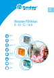
Datasheet


A
Power relays 1 and 2 pole for direct PCB or
socket mount
Type 40.62
- 2 CO 10A (5.0 mm pin pitch)
- DC coils (650 mW or 500 mW)
- Meets EN 60335-1 glow wire requirements
Type 40.11
- 1 CO 10 A - flat pack
- DC (sensitive) coils
Type 40.xx.6
- Bistable versions of the types 40.31, 40.51,
40.52 and 40.61
- Bistable (single coil)
• Cadmium-free contact material available
• 8 mm Creepage and Clearance, 6 kV (1.2/50µs)
between coil and contact
• 95 series sockets for PCB or 35 mm rail mounting
(EN 60715) with Screw, Screwless or Push-in
terminals
• Environmental protection:
RT II - flux proof (Standard)
RT III - wash tight (Option)
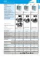
40.62
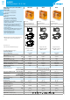
40.xx.6
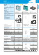
40.11
• 2 CO 10 A
• 5.0 mm pin pitch
• PCB or 95 Series sockets mount
• Bistable (single coil)
• 3.5 or 5.0 mm pin pitch
• PCB or 95 Series socket mount
• 1 CO 10 A
• PCB mount 12.7 mm high
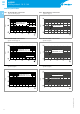
Copper side view
Pin length 5.3mm for
PCB or sockets
Bistable version (1 coil) types:
40.31.6…
40.51.6…
40.52.6…
40.61.6…
For wiring diagrams see page 11
Pin length 5.3mm for
PCB or sockets
Copper side view
Pin length 3.5mm for PCB
For UL ratings see:
“General technical information” page V
For outline drawing see page 12
Contact specification
Contact configuration 2 CO (DPDT) 1 CO (SPDT)
Rated current/Maximum peak current A 10/20 10/20
Rated voltage/
Maximum switching voltage VAC 250/400 See relays 250/400
Rated load AC1 VA 2500 40.31 2500
Rated load AC15 (230VAC) VA 750 40.51 500
Single phase motor rating (230VAC) kW 0.37 40.52 0.37
Breaking capacity DC1: 30/110/220V A 10/0.6/0.25 40.61 10/0.3/0.12
Minimum switching load mW (V/mA) 300 (5/5) page 4 300 (5/5)
Standard contact material AgNi AgCdO
Coil specification
Nominal voltage (U
N
) VAC (50/60Hz) —
5 - 6 - 12 - 24 - 48 - 110
—
VDC
5 - 6 - 7 - 9 - 12 - 14 - 18 - 21 - 24
- 28 - 48 - 60 - 110 - 125 6 - 12 - 24 - 48 - 60
Rated power AC/DC/sens. DC VA (50Hz)/W/W —/0.65/0.5 1.0/1.0/— —/—/0.5
Operating range AC — (0.8…1.1)U
N
—
DC/sens. DC (0.73…1.5)U
N
/(0.73..1.5) U
N
(0.8…1.1)U
N
/— —/(0.73…1.75)U
N
Holding voltage AC/DC —/0.4U
N
— —/0.4U
N
Must drop-out voltage AC/DC —/0.1U
N
— —/0.1U
N
Technical data
Mechanical life cycles 10·10
6
See relays 20·10
6
Electrical life at rated load AC1 cycles 100·10
3
40.31 200·10
3
Operate/release time ms 7/3 (12/4 sensitive) 40.51 12/4
Insulation between coil
and contacts (1.2/50µs) kV 6 (8mm) 40.52 6 (8mm)
Dielectric strength
between open contacts VAC 1000 40.61 1000
Ambient temperature range °C –40…+85 Min. impulse duration –40…+70
Environmental protection RT II ≥20ms RT I**
Approvals (according to type)
** See general technical information “Guidelines for automatic flow solder processes” page II.
5
VIII-2019, www.findernet.com
40
SERIES
40 SERIES
PCB/Plug-in relays 8 - 10 - 12 - 16A