
Datasheet

40.31 40.51 40.52
1 CO (SPDT) 1 CO (SPDT) 2 CO (DPDT)
10/20 10/20 8/15
250/400 250/400 250/400
2,500 2,500 2,000
500 500 400
0.37 0.37 0.3
10/0.3/0.12 10/0.3/0.12 8/0.3/0.12
300 (5/5) 300 (5/5) 300 (5/5)
AgNi AgNi AgNi
6 - 12 - 24 - 48 - 60 - 110 - 120 - 230 - 240
5 - 6 - 7 - 9 - 12 - 14 - 18 - 21 - 24 - 28 - 36 - 48 - 60 - 90 - 110 - 125
1.2/0.65/0.5 1.2/0.65/0.5 1.2/0.65/0.5
(0.8…1.1)U
N
(0.8…1.1)U
N
(0.8…1.1)U
N
(0.73…1.5)U
N
/(0.73…1.5)U
N
(0.73…1.5)U
N
/(0.73…1.5)U
N
(0.73…1.5)U
N
/(0.73…1.5)U
N
0.8
U
N
/0.4
U
N
0.8
U
N
/0.4
U
N
0.8
U
N
/0.4
U
N
0.2
U
N
/0.1
U
N
0.2
U
N
/0.1
U
N
0.2
U
N
/0.1
U
N
10 · 10
6
10 · 10
6
10 · 10
6
200 · 10
3
200 · 10
3
100 · 10
3
7/3 - (12/4 sensitive) 7/3 - (12/4 sensitive) 7/3 - (12/4 sensitive)
6 (8 mm) 6 (8 mm) 6 (8 mm)
1,000 1,000 1,000
–40…+85 –40…+85 –40…+85
RT II** RT II** RT II**
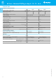
Contact specification
Contact configuration
Rated current/Maximum peak current A
Rated voltage/Maximum switching voltage
V AC
Rated load AC1 VA
Rated load AC15 (230 V AC) VA
Single phase motor rating (230 V AC) kW
Breaking capacity DC1: 30/110/220 V A
Minimum switching load mW (V/mA)
Standard contact material
Coil specification
Nominal voltage (U
N
) V AC (50/60 Hz)
V DC
Rated power AC/DC/sens. DC VA (50 Hz)/W/W
Operating range AC
DC/sens. DC
Holding voltage AC/DC
Must drop-out voltage AC/DC
Technical data
Mechanical life cycles
Electrical life at rated load AC1 cycles
Operate/release time ms
Insulation between coil and contacts (1.2/50 µs)
kV
Dielectric strength between open contacts V AC
Ambient temperature range °C
Environmental protection
Approvals (according to type)
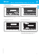
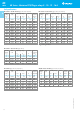
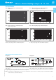
Copper side view Copper side view Copper side view
Pin length 5.3 mm for Pin length 5.3 mm for Pin length 5.3 mm for
PCB or sockets PCB or sockets PCB or sockets
1
** See general technical information “Guidelines for automatic flow solder processes” page II .
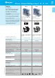
• 3.5 mm contact pin pitch
• 1 Pole 10 A
• PCB or 95 series sockets
Features
1 & 2 Pole relay range
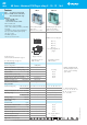
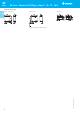
40.31 - 1 Pole 10 A (3.5 mm pin pitch)
40.51 - 1 Pole 10 A (5 mm pin pitch)
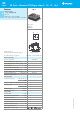
40.52 - 2 Pole 8 A (5 mm pin pitch)
PCB mount
- direct or via PCB socket
35 mm rail mount
- via screw and screwless sockets
• DC coils (standard or sensitive) & AC coils
• Cadmium Free contact material
• 8 mm, 6 kV (1.2/50 µs) isolation, coil-contacts
• UL Listing (certain relay/socket combinations)
• Flux proof: RT II standard, (RT III option)
• 95 series sockets
• Coil EMC suppression
• Timer accessories 86 series
• 5 mm contact pin pitch
• 1 Pole 10 A
• PCB or 95 series sockets
• 5 mm contact pin pitch
• 2 Pole 8 A
• PCB or 95 series sockets
FOR UL RATINGS SEE:
“General technical information” page V
For outline drawing see page 10
VI-2014, www.findernet.com
40 Series - Miniature PCB/Plug-in relays 8 - 10 - 12 - 16 A
40
SERIES
A