
Datasheet

40.61 40.xx.6
2
1 CO (SPDT)
16/30*
250/400 See relays
4,000 40.31
750 40.51
0.55 40.52
16/0.3/0.12 40.61
500 (10/5)
AgCdO
6 - 12 - 24 - 48 - 60 - 110 - 120 - 230 - 240
5 - 6 - 12 - 24 - 48 - 110
***See table 5 - 6 - 12 - 24 - 48 - 110
1.2/0.65/0.5 1.0/1.0/—
(0.8…1.1)U
N
(0.8…1.1)U
N
(0.73…1.5)U
N
/(0.8…1.5)U
N
(0.8…1.1)U
N
/—
0.8 U
N
/0.4 U
N
—
0.2 U
N
/0.1 U
N
—
10 · 10
6
See relays
100 · 10
3
40.31
7/3 - (12/4 sensitive) 40.51
6 (8 mm) 40.52
1,000 40.61
–40…+85 Min. impulse duration
RT II** ≥ 20 ms
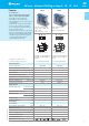
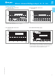
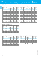
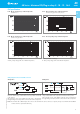
Bistable version (1 coil) types:
40.31.6...
40.51.6...
40.52.6...
40.61.6...
For wiring diagrams see
page 9
*** Nominal voltage (U
N
):
5 - 6 - 7 - 9 - 12 - 14 - 18 - 21 -
24 - 28 - 36 - 48 - 60 - 90 -
110 - 125
V DC
* With the AgSnO
2
material
the
maximum peak
current is
120 A - 5 ms on normally
open contact.
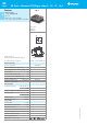
Copper side view
Pin length 5.3 mm for Pin length 5.3 mm for
PCB or sockets PCB or sockets
** See general technical information “Guidelines for automatic flow solder processes” page II.
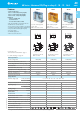
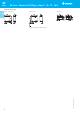
• 5 mm contact pin pitch
• 1 Pole 16 A
• PCB or 95 series sockets
Features
40.61 - 1 Pole 16 A (5 mm pin pitch)
40.xx.6 - Bistable versions of the 40.31,
40.51, 40.52 & 40.61 relays
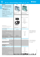
PCB mount
- direct or via PCB socket
35 mm rail mount
- via screw and screwless sockets
• DC coils & AC coils
• Cadmium Free option available
• 8 mm, 6 kV (1.2/50 µs) isolation, coil-contacts
• UL Listing
(certain 40.61 relay/socket combinations)
• Flux proof: RT II standard, (RT III option)
• 95 series sockets
• Coil EMC suppression
• Timer accessories 86 series
• Bistable (single coil) versions
of 40.31/51/52/61
• PCB or 95 series sockets
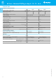
Contact specification
Contact configuration
Rated current/Maximum peak current A
Rated voltage/Maximum switching voltage
V AC
Rated load AC1 VA
Rated load AC15 (230 V AC) VA
Single phase motor rating (230 V AC) kW
Breaking capacity DC1: 30/110/220 V A
Minimum switching load mW (V/mA)
Standard contact material
Coil specification
Nominal voltage (U
N
) V AC (50/60 Hz)
V DC
Rated power AC/DC/sens. DC VA (50 Hz)/W/W
Operating range AC
DC/sens. DC
Holding voltage AC/DC
Must drop-out voltage AC/DC
Technical data
Mechanical life cycles
Electrical life at rated load AC1 cycles
Operate/release time ms
Insulation between coil and contacts (1.2/50 µs)
kV
Dielectric strength between open contacts V AC
Ambient temperature range °C
Environmental protection
Approvals (according to type)
FOR UL RATINGS SEE:
“General technical information” page V
For outline drawing see page 10
VI-2014, www.findernet.com
40
SERIE S
40 Series - Miniature PCB/Plug-in relays 8 - 10 - 12 - 16 A
A