
Datasheet
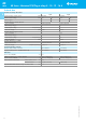

Contact specification
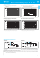
Cycles
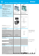
F 40 - Electrical life (AC) v contact current
Types 40.31/51/61
• When switching a resistive load (DC1) having voltage and current
values under the curve, an electrical life of ≥ 100·10
3
can be expected.
• In the case of DC13 loads, the connection of a diode in parallel with
the load will permit a similar electrical life as for a DC1 load.
Note: the release time for the load will be increased.
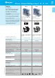
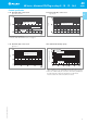
F 40 - Electrical life (AC) v contact current
Type 40.52
H 40 - Maximum DC1 breaking capacity
DC breaking current (A)
DC voltage (V)
Cycles
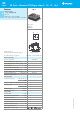
F 40 - Electrical life (AC) v contact current
Type 40.11
Resistive load - cosϕ = 1
Inductive load - cosϕ = 0.4
40.52 - 2 contacts in series
single contact
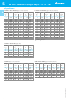
40.61 current limit
40.11/31/51 current limit
40.52 current limit
7
VI-2014, www.findernet.com
Cycles
**Inductive
load - AC15
*limit for 40.31
limit for 40.31/51
Resistive load - cosϕ = 1
Inductive load - cosϕ = 0.4
* limit for 40.31, see page 3
** Inductive load - AC15 for 40.31/61, see page 3
Resistive load - cosϕ = 1
Inductive load - cosϕ = 0.4
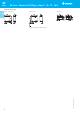
40 Series - Miniature PCB/Plug-in relays 8 - 10 - 12 - 16 A
40
SERIES
A