
Datasheet
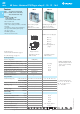
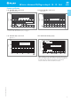
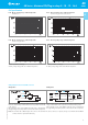

Wiring diagram for 40 series bistable coil version
On momentary closure of the SET switch the relay is magnetised through
the diode and the relay contacts transfer to the set position and remain
in this position.
On momentary closure of the RESET switch the relay is demagnetised
through limiting resistor (R
AC
) and the contacts return to the reset position.
On momentary closure of the SET switch the relay is magnetised and the
relay contacts transfer to the set position and remain in this position.
On momentary closure of the RESET switch the relay is demagnetised
through limiting resistor (R
DC
) and the contacts return to the reset position.
Notes: The minimum SET or RESET impulse time is 20 ms. The maximum time can be continuous. In practice, always ensure that the SET and RESET
contacts cannot be operated simultaneously.
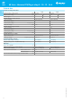
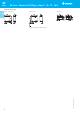
Coil specifications
AC Operation DC Operation
1 - Max. permitted coil voltage.
2 - Min. pick-up voltage with coil at ambient temperature.
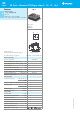
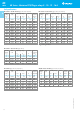
R 40 - DC coil operating range v ambient temperature
Sensitive coil, types 40.31/51/52/61
R 40 - DC coil operating range v ambient temperature
Standard coil
R 40 - AC coil operating range v ambient temperatureR 40 - DC coil operating range v ambient temperature
Sensitive coil, type 40.11
1 - Max. permitted coil voltage.
2 - Min. pick-up voltage with coil at ambient temperature.
9
VI-2014, www.findernet.com
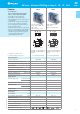
40.61
40.31/51/52
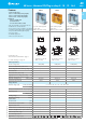
40 Series - Miniature PCB/Plug-in relays 8 - 10 - 12 - 16 A
40
SERIES
A