
Data Sheet


B
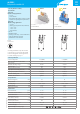
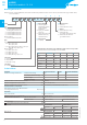
Ordering information
Example: 48 series, 35mm rail (EN60715) mount, Push-in terminal relay interface module, 2 CO 8A contacts, 24V sensitive DC coil, green LED + diode,
99.02 coil indication.
A B C D
4 8 . P 5 . 7 . 0 2 4 . 0 0 5 0
Series
Type
Screw terminal
1 = 35 mm rail (EN60715) mount,
forcibly guided contacts relay
3 = 35 mm rail (EN60715) mount
5 = 35 mm rail (EN60715) mount
6 = 35 mm rail (EN60715) mount
Push-in terminal
P = 35 mm rail (EN60715) mount
Type
Screw terminal
1 = for 48.31, 1 pole, 10A
48.61, 1 pole, 16A
2 = for 48.12/48.32 (DC only), 48.52, 2 poles, 8 A
48.62 (DC only), 2 poles, 10 A
Push-in terminal
3 = for 48.P3, 1 pole, 10A
5 = for 48.P5, 2 pole, 8 A
6 = for 48.P6, 1 pole, 16A
8 = for 48.P8 (DC only), 2 pole, 10A
Coil version
7 = Sensitive DC
8 = AC (50/60 Hz)
9 = DC (for 48.12 only)
Coil voltage
See coil specifications
A: Contact material
0 = Standard AgNi for
48.P3/P5/P8/31/52/62
AgCdO, Standard
for 48.P6/61
4 = AgSnO
2
, for 48.P6/P8/
61/62 only
5 = AgNi + Au, for 48.12 and
48.P3/P5/31/52 only
Standard for 48.32
B: Contact circuit
0 = CO (nPDT)
D: Special versions
0 = Standard
7 = Standard (for 48.12 only)
C: Options
0 = Standard (for 48.12 only)
5 = Standard for DC:
green LED + diode (polarity +A1)
6 = Standard for AC and 48.32:
green LED + Varistor
Selecting features and options: only combinations in the same row are possible.
Preferred selections for best availability are shown in bold.
Type Coil version A B C D
48.12 DC 5 0 6 7
48.32 DC 5 0 6 0
48.P3/P5/31/52 AC 0 - 5 0 6 0
48.P3/P5/31/52 Sensitive DC 0 - 5 0 5 0
48.P6/61 AC 0 - 4 0 6 0
48.P6/61 Sensitive DC 0 - 4 0 5 0
48.P8/62 Sensitive DC 0 - 4 0 5 0
Technical data
Insulation 48.12/31/32/61/P3/P6 48.52/P5 48.12/31/61/62/P3/P6/P8
Insulation according to EN61810-1 insulation rated voltage V 250 250 400
rated impulse withstand voltage kV 4 4 4
pollution degree 3 2 2
overvoltage category III III III
Insulation between coil and contacts (1.2/50µs) kV 6 (8mm)
Dielectric strength between open contacts VAC 1000; 1500 (48.12/32)
Dielectric strength between adjacent contacts VAC 2000 (48.P5/52); 2500 (48.P8/62) 3000 (48.12/32)
Insulation between coil terminals
Rated impulse voltage (surge) differential mode
(according to EN 61000-4-5) kV(1.2/50µs) 2
Other data
Bounce time: NO/NC ms 2/5; 2/10 (48.12/32)
Vibration resistance (10…200)Hz: NO/NC g 20/5 (for 1 pole) 15/3; 20/6 (48.12/32) for 2 pole
Power lost to the environment without contact current W 0.7
with rated current W
1.2 (48.12/31/32/P3)
2 (48.52/P5/61/62/P6/P8)
Wire strip length mm 8
Screw torque (only for 48.12/31/32/52/61/81) Nm 0.5
Min. wire size Screw terminal Push-in terminal
solid cable stranded cable solid cable stranded cable
mm
2
0.5 0.5 0.5 0.5
AWG 21 21 21 21
Max. wire size Screw terminal Push-in terminal
solid cable stranded cable solid cable stranded cable
mm
2
1x6 / 2x2.5 1x4 / 2x2.5 2x1.5 / 1x2.5 2x1.5 / 1x2.5
AWG 1x10 / 2x14 1x12 / 2x14 2x16 / 1x14 2x16 / 1x14
8
VII-2018, www.findernet.com
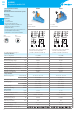
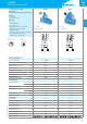
48 SERIES
Relay interface modules 8 - 10 - 16A
48
SERIES