
Datasheet


X-2018, www.findernet.com
B
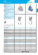
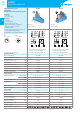
2 CO relay interface modules,
15.8 mm wide
Type 48.12
Ideal for safety applications
- 2 CO 8 A
- Screw terminals
- Relay with forcibly guided contacts according
to EN 61810-3 Type B (previously EN 50205)
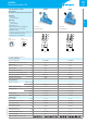
Type 48.32
Ideal for energy applications
- 2 CO 8 A
- Breaking capacity DC inductive (L/R=40 ms)
- 110 V = 0.5 A
- 220 V = 0.2 A
- Screw terminals
• DC coils
• Identification label
• UL Listing (certain relay / socket combinations)
• 35 mm rail (EN 60715) mounting
• Cadmium-free contact material
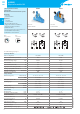
48.12/32
Screw terminal
48.12 48.32
• 2 CO 8A
• Screw terminals
• 2 CO 8A
• Screw terminals
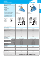
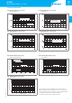
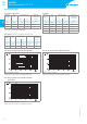
48.12
48.12
According to EN 61810-3 only 1 NO and 1 NC
(11-14 and 21-22 or 11-12 and 21-24) shall be
used as forcibly guided contacts (Type 48.12).
For outline drawing see page 11
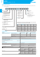
Contact specification
Contact configuration 2 CO (DPDT) 2 CO (DPDT)
Rated current/Maximum peak current A 8/15 8/15
Rated voltage/
Maximum switching voltage VAC 250/400 250/400
Rated load AC1 VA 2000 2000
Rated load AC15 (230VAC) VA 500 500
Single phase motor rating (230VAC) kW 0.37 0.37
Breaking capacity DC1: 30/110/220V A 8/0.65/0.4 8/0.65/0.4
Minimum switching load mW (V/mA) 50 (5/5) 50 (5/5)
Standard contact material AgNi+Au AgNi+Au
Coil specification
Nominal voltage (U
N
) VDC 24 24
Rated power DC W 0.7 0.7
Operating range DC (0.75…1.2)U
N
(0.75…1.2)U
N
Holding voltage DC 0.4U
N
0.4U
N
Must drop-out voltage DC 0.1U
N
0.1U
N
Technical data
Mechanical life DC cycles 10·10
6
10·10
6
Electrical life at rated load AC1 cycles 100·10
3
100·10
3
Operate/release time ms 10/4 10/4
Insulation between coil
and contacts (1.2/50µs) kV 6 (8mm) 6 (8mm)
Dielectric strength
between open contacts VAC 1500 1500
Ambient temperature range °C –40…+70 –40…+70
Protection category IP 20 IP 20
Approvals relay (according to type)
3
48
SERIES
48 SERIES
Relay interface modules 8A