
Data Sheet


II-2016, www.findernet.com
4
B
4C SERIES
Relay interface modules 8 to 16A
4C
SERIES
Contact specification
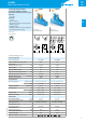
F 4C - Electrical life (AC) v contact current
Types 4C.02/P2
F 4C - Electrical life (AC) v contact current
Types 4C.01/P1
Cycles
Resistive load - cosφ = 1
Inductive load - cosφ = 0.4
Cycles
Resistive load - cosφ = 1
Inductive load - cosφ = 0.4
limit for 4C.P1
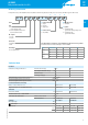
H 4C - Maximum DC1 breaking capacity
Current limit 1 CO (SPDT) (*)
Current limit 2 CO (DPDT)
DC breaking current (A)
DC voltage (V)
(*) Type 4C.01=12A, Type 4C.P1=10A
• When switching a resistive load (DC1) having voltage and current
values under the curve, an electrical life of ≥100·10
3
can be expected.
• In the case of DC13 loads, the connection of a diode in parallel with the
load will permit a similar electrical life as for a DC1 load.
Note: the release time for the load will be increased.
Coil specifications
DC coil data
Nominal
voltage
Coil code Operating range Resistance Rated coil
consumption
U
N
U
min
U
max
R I at U
N
V V V
Ω
mA
12 9.012 8.8 13.2 300 40
24 9.024 17.5 26.4 1200 20
125 9.125 91.2 138 32000 3.9
AC coil data
Nominal
voltage
Coil code Operating range Resistance Rated coil
consumption
U
N
U
min
U
max
R I at U
N
V V V
Ω
mA
12 8.012 9.6 13.2 80 90
24 8.024 19.2 26.4 320 45
110 8.110 88 121 6900 9.4
120 8.120 96 132 9000 8.4
230 8.230 184 253 28000 5
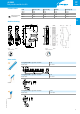
R 4C - DC coil operating range v ambient temperature R 4C - AC coil operating range v ambient temperature
Single Pole Relay
Contact Current
limited to 12A
Single Pole Relay
Contact Current
limited to 12A
1 - Max. permitted coil voltage.
2 - Min. pick-up voltage with coil at ambient temperature.
1 - Max. permitted coil voltage.
2 - Min. pick-up voltage with coil at ambient temperature.
------ Temperature limit for the single pole version under full 16A contact current.