
Datasheet


4
Contact specification
Nominal Coil Operating range Resistance Rated coil
voltage code absorption
U
N
U
min
U
max
R
I at U
N
(50Hz)
VVVΩ mA
12 8.012 9.6 13.2 50 97
24 8.024 19.2 26.4 190 53
48 8.048 38.4 52.8 770 25
110 8.110 88 121 4,000 12.5
120 8.120 96 132 4,700 12
230 8.230 184 253 17,000 6
Nominal Coil Operating range Resistance Rated coil
voltage code absorption
U
N
U
min
U
max
R I at U
N
VVVΩ mA
12 9.012 9.6 13.2 140 86
24 9.024 19.2 26.4 600 40
48 9.048 38.4 52.8 2,400 20
125 9.125 100 138 17,300 7.2
AC coil dataDC coil data
Coil specifications
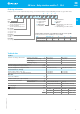
F 58 - Electrical life (AC) v contact current
2 & 3 pole relays
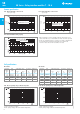
H 58 - Maximum DC1 breaking capacity
• When switching a resistive load (DC1) having voltage and current
values under the curve, an electrical life of ≥ 100·10
3
can be expected.
• In the case of DC13 loads, the connection of a diode in parallel with
the load will permit a similar electrical life as for a DC1 load.
Note: the release time for the load will be increased.
1 - Max. permitted coil voltage.
2 - Min. pick-up voltage with coil at ambient temperature.
R 58 - DC coil operating range v ambient temperature R 58 - AC coil operating range v ambient temperature
1 - Max. permitted coil voltage.
2 - Min. pick-up voltage with coil at ambient temperature.
F 58 - Electrical life (AC) v contact current
4 pole relay
Cycles
Resistive load - cosϕ = 1
Inductive load - cosϕ = 0.4
Cycles
Resistive load - cosϕ = 1
Inductive load - cosϕ = 0.4
DC voltage (V)
DC breaking current (A)
contacts in series
2 & 3 pole current limit
4 pole current limit
4
3
2
1
1
2
1
2
II-2014, www.findernet.com
58
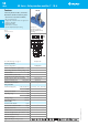
SERIE S
58 Series - Relay interface modules 7 - 10 A
B