
Datasheet

2
B
58 SERIES
Relay interface modules 7-10A
58
SERIES
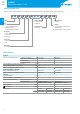
Ordering information
Example: 58 series, 35mm rail (EN60715) mounting, Push-in terminals interface module, 4CO (4PDT), 24VDC coil, green LED + diode.
A B C D
5 8 . P 4 . 9 . 0 2 4 . 0 0 5 . 0
Series
Type
3 = Screw terminals
35mm rail (EN60715) mount
P = Push-in terminals
35mm rail (EN60715) mount
No. of poles
2 = 2 pole, 10A
3 = 3 pole, 10A
4 = 4 pole, 7A
Coil version
8 = AC (50/60Hz)
9 = DC
Coil voltage
See coil specifications
A: Contact material
0 = AgNi Standard
5 = AgNi + Au
B: Contact circuit
0 = CO (nPDT)
D: Special versions
0 = Standard
C: Options
5 = Standard DC: green LED + diode
(polarity +A1)
6 = Standard AC: green LED + Varistor
B
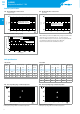
Technical data
Insulation
Insulation according to EN61810-1 insulation rated voltage V 400 (2-3 pole) 250 (4 pole)
rated impulse withstand voltage kV 3.6 (2-3 pole) 2.5 (4 pole)
pollution degree 2 2
overvoltage category III II
Insulation between coil and contacts (1.2/50μs) kV 3.6
Dielectric strength between open contacts V AC 1000
Dielectric strength between adjacent contacts V AC 2000 (58.32,58.33) 1550 (58.34, 58.54)
Conducted disturbance immunity
Burst (5…50)ns, 5kHz, on A1 - A2 EN61000-4-4 level 4 (4kV)
Surge (1.2/50μs) on A1 - A2 (differential mode) EN61000-4-5 level 4 (4kV)
Other data
Bounce time: NO/NC ms 1/3
Vibration resistance (10…55)Hz: NO/NC g 6/6
Power lost to the environment without contact current W 1
with rated current W 3 (58.32, 58.34, 58.P4) 4 (58.P3, 58.33)
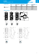
58.32/33/34 (screw terminals) 58.P3/P4 (Push-in terminals)
Wire strip length mm 8 8
Screw torque Nm 0.5 —
Max. wire size solid cable stranded cable solid cable stranded cable
mm
2
1x6 / 2x2.5 1x4 / 2x2.5 2x(0.5…1.5) 2x(0.5…1.5)
AWG 1x10 / 2x14 1x12 / 2x14 2x(21…14) 2x(21…14)