
Data Sheet
66.22 66.82
2 CO (DPDT) 2 CO (DPDT)
30/50 (NO) - 10/20 (NC) 30/50 (NO) - 10/20 (NC)
250/440 250/440
7,500 (NO) - 2,500 (NC) 7,500 (NO) - 2,500 (NC)
1,200 (NO) 1,200 (NO)
1.5 (NO) 1.5 (NO)
25/0.7/0.3 (NO) 25/0.7/0.3 (NO)
1,000 (10/10) 1,000 (10/10)
AgCdO AgCdO
6 - 12 - 24 - 110/115 - 120/125 - 230 - 240
6 - 12 - 24 - 110 - 125
3.6/1.7 3.6/1.7
(0.8…1.1)U
N
(0.8…1.1)U
N
(0.8…1.1)U
N
(0.8…1.1)U
N
0.8 U
N
/0.5 U
N
0.8 U
N
/0.5 U
N
0.2 U
N
/0.1 U
N
0.2 U
N
/0.1 U
N
10 · 10
6
10 · 10
6
100 · 10
3
100 · 10
3
8/15 8/15
6 (8 mm) 6 (8 mm)
1,500 1,500
–40…+70 –40…+70
RT II RT II
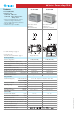
• 30 A rated contacts
• Flange mount
• Faston 250 connections
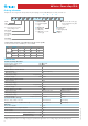
Contact specification
Contact configuration
Rated current/Maximum peak current A
Rated voltage/Maximum switching voltage V AC
Rated load AC1 VA
Rated load AC15 (230 V AC) VA
Single phase motor rating (230 V AC) kW
Breaking capacity DC1: 30/110/220 V A
Minimum switching load mW (V/mA)
Standard contact material
Coil specification
Nominal voltage (U
N
) V AC (50/60 Hz)
V DC
Rated power AC/DC VA (50 Hz)/W
Operating range AC
DC
Holding voltage AC/DC
Must drop-out voltage AC/DC
Technical data
Mechanical life AC/DC cycles
Electrical life at rated load AC1 cycles
Operate/release time ms
Insulation between coil and contacts (1.2/50
μ
s)
kV
Dielectric strength between open contacts V AC
Ambient temperature range °C
Environmental protection
Approvals (according to type)
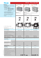
Copper side view
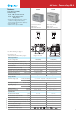
Features
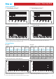
2 Pole Changeover (DPDT)
30 A Power relay
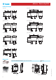
66.22 PCB connections & mount
66.82 Faston 250 connections
- Flange mount
• Reinforced insulation between coil and
contacts according to EN 60335-1;
8 mm creepage and clearance distances
• AC coils & DC coils
• Cadmium Free option available
• 30 A rated contacts
• PCB mount -
bifurcated terminals
1
For outline drawing see page 6
F
OR UL RATINGS SEE:
“General technical information” page V
66 Series - Power relays 30 A
VII-2012, www.findernet.com