
Data Sheet

Coil specifications
Contact specification
Nominal Coil Operating range Resistance Rated coil
voltage code
consumption
U
N
U
min
U
max
R
I at U
N
(50Hz)
VVVΩ mA
6 8.006 4.8 6.6 3 600
12 8.012 9.6 13.2 11 300
24 8.024 19.2 26.4 50 150
110/115 8.110 88 126 930 32.6
120/125 8.120 96 137 1,050 30
230 8.230 184 253 4,000 15.7
240 8.240 192 264 5,500 15
AC coil data
Nominal Coil Operating range Resistance Rated coil
voltage code
consumption
U
N
U
min
U
max
R I at U
N
VVVΩ mA
6 9.006 4.8 6.6 21 283
12 9.012 9.6 13.2 85 141
24 9.024 19.2 26.4 340 70.5
110 9.110 88 121 7,000 15.7
125 9.125 100 138 9,200 13.6
DC coil data
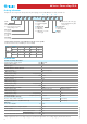
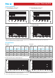
F 66 - Electrical life (AC) v contact current
250 V (normally open contact)
66 Series - Power relay 30 A
Cycles
F 66 - Electrical life (AC) v contact current
440 V (normally open contact)
Cycles
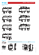
• When switching a resistive load (DC1) having voltage and current values under the curve, an electrical life of ≥ 100·10
3
can be expected.
• In the case of DC13 loads, the connection of a diode in parallel with the load will permit a similar electrical life as for a DC1 load.
Note: the release time for the load will be increased.
H 66 - Maximum DC breaking capacity
DC breaking current (A)
DC voltage (V)
H 66 - Maximum DC breaking capacity, x600 versions
(>1.5mm contact gap)
DC breaking current (A)
DC voltage (V)
R 66 - DC coil operating range v ambient temperature
1 - Max. permitted coil voltage.
2 - Min. pick-up voltage with coil at ambient temperature.
3 - Min. pick-up voltage with coil at ambient temperature (66.22-x600S).
R 66 - AC coil operating range v ambient temperature
1 - Max. permitted coil voltage.
2 - Min. pick-up voltage with coil at ambient temperature.
Resistive load - 250 V AC cosϕ = 1
Inductive load - 250 V AC cosϕ = 0.4
Resistive load - 440 V AC cosϕ = 1
Inductive load - 440 V AC cosϕ = 0.4
5
VII-2012, www.findernet.com