
Data Sheet

3
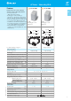
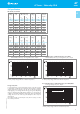
Example: 67 series solar relay, single PCB terminals, 2 pole NO, ≥ 3 mm contact gap .
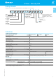
Ordering information
A: Contact material
4 = Standard AgSnO
2
B: Contact circuit
3 = NO, ≥ 3 mm contact gap
5 = NO, ≥ 5.2 mm contact gap
Series
Type
2= Single PCB terminals, 1.5 mm gap
between PCB and relay base
No. of poles
2 = 2 pole
3 = 3 pole
Coil version
9 = DC
Coil voltage
See coil specifications
2 3 4 39
D: Special versions
0 = Standard
1 = Wash tight (RTIII)
C: Options
0 = None
S = Version suggested for 100 A
switching, provided the
3 contacts are connected in
parallel (only 67.23...430xS)
0 0
ABCD
... .
01267
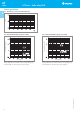
Insulation according to EN 61810-1
Nominal voltage of supply system V AC 400/690 3-phase 400 1-phase 230/400
Rated insulation voltage V AC 630 400 400
Pollution degree 3
Insulation between coil and contact set
Type of Insulation Reinforced
Overvoltage category III
Rated impulse voltage kV (1.2/50 µs) 6
Dielectric strength V AC 4,000
Insulation between adjacent contacts
Type of Insulation Basic
Overvoltage category III
Rated impulse voltage kV (1.2/50) s 6
Dielectric strength V AC 2,500
Insulation between open contacts
Type of disconnection Micro-disconnection * Full-disconnection
Overvoltage category — III
Rated impulse voltage kV (1.2/50) s — 4
Dielectric strength V AC 2,500 (67.xx-4300) / 3,000 (67.xx-4500)
Other data
Bounce time: NO ms 2
Vibration resistance (10...150)Hz: NO g 15
Shock resistance g 35
Power lost to the environment without contact current W 1.7 (67.xx-4300) / 2.7 (67.xx-4500)
with rated current W 8.5 (67.xx-4300) / 9.5 (67.xx-4500)
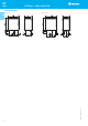
Recommended distance between relays mounted on PCB mm ≥ 20
* with overvoltage category II: Full-disconnection
Technical data
II-2014, www.findernet.com
A
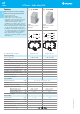
67 Series - Solar relay 50 A
67
SERIES