
Data Sheet

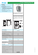


L1
13 5 7 9
A1
24 6810
14 12 11
3~U ASY
U= 400 V AC 3
~
(50/60 Hz )
L2
L3
A2 A3
3
3 - Phase 400 V - Line monitoring relays
71.31.8.400.1021
- Over & Under voltage trip on-delay
- Fault memory
71.31.8.400.2000
- Phase asymmetry
- Phase rotation
- Phase loss
• 35 mm rail (EN 60715) mounting
• LED indication
• Positive safety logic (healthy conditions -
output relay energised)
Features
1 CO (SPDT) 1 CO (SPDT)
10/15 10/15
250/400 250/400
2,500 2,500
500 500
0.5 0.5
10/0.3/0.12 10/0.3/0.12
300 (5/5) 300 (5/5)
AgCdO AgCdO
400 400
——
4/ — 4/—
(0.8…1.15)U
N
(0.8...1.15)U
N
——
100 · 10
3
100 · 10
3
(0.8...0.95)U
N
/ 1.15 U
N
/— 0.8 U
N
/ 1.11 U
N
/(–5...–20)% U
N
(0.1...12)s / < 0.5 s — / < 0.5 s
Yes —
None – circuits are electrically common None – circuits are electrically common
–20...+55 –20...+55
IP 20 IP 20
• 3 phase 400 V - line voltage monitoring
• Detects over and under voltage
• Adjustable trip on-delay
• Switch selectable fault memory
• Under voltage trip level (0.8...0.95)U
N
-
Adjustable
• Over voltage trip level 1.15 U
N
- Fixed
• Trip delay time (0.1…12)s adjustable
• Fault memory, switch selectable
• Fault acknowledgement by switch manipulation
from ON to OFF and back to ON or power
down
Contact specification
Contact configuration
Rated current/Maximum peak current A
Rated voltage/Maximum switching voltage V AC
Rated load AC1 VA
Rated load AC15 (230 V AC) VA
Single phase motor rating (230 V AC) kW
Breaking capacity DC1: 30/110/220 V A
Minimum switching load mW (V/mA)
Standard contact material
Supply specification
Nominal voltage (U
N
) V AC (50/60 Hz)
V DC
Rated power AC/DC VA (50 Hz)/W
Operating range AC
DC
Technical data
Electrical life at rated load AC1 cycles
Detection level U
min
/U
max
/Asymmetry
Trip on-delay/reaction time
Fault memory - selectable
Electrical isolation: Supply to Measuring circuits
Ambient temperature range °C
Protection category
Approvals (according to type)
• 3 phase asymmetry monitoring
• Phase rotation monitoring
• Phase loss monitoring
• Asymmetry between phases (–5… –20)% U
N
adjustable
• Detection of the supply voltage
U to A1 (1) and/or A2 (5) > 1.11 U
N
71 Series - Monitoring relays 10 A
71.31.8.400.1021 71.31.8.400.2000
XI-2012, www.findernet.com