
Datasheet


H
Functions
U = Supply voltage
S = Signal switch
= Output contact
LED* Supply voltage
NO output
contact
Contacts
Open Closed
OFF Open 15 - 18 15 - 16
ON Open 15 - 18 15 - 16
ON
Open
(Timing in Progress)
15 - 18 15 - 16
ON Closed 15 - 16 15 - 18
* The LED on type 80.61 is illuminated only when the supply voltage is applied to the timer; during the timing period the LED
is not illuminated.
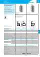
Wiring diagram
Without control signal = Start via contact in supply line (A1).
With control signal = Start via contact into control terminal (B1).
Without control signal
80.01
80.51
80.71
Type
80.01
80.51
80.71
(AI) On-delay.
Apply power to timer. Output contacts transfer after preset
time has elapsed. Reset occurs when power is removed.
(DI) Interval.
Apply power to timer. Output contacts transfer immediately.
After the preset time has elapsed, contacts reset.
(SW) Symmetrical flasher (starting pulse on).
Apply power to timer. Output contacts transfer immediately
and cycle between ON and OFF for as long as power is applied.
The ratio is 1:1 (time on= time off).
With control signal
80.01
80.51
80.71
80.01
80.51
80.71
(BE) Off-delay with control signal.
Power is permanently applied to the timer. The output
contacts transfer immediately on closure of the Signal Switch
(S). Opening the Signal Switch initiates the preset delay, after
which time the output contacts reset.
(CE) On- and off-delay with control signal.
Power is permanently applied to the timer. Closing the Signal
Switch (S) initiates the preset delay, after which time the output
contacts transfer. Opening the Signal switch initiates the same
preset delay, after which time the output contacts reset.
(DE) Interval with control signal on.
Power is permanently applied to the timer.
On momentary or maintained closure of Signal Switch (S), the
output contacts transfer, and remain so for the duration of the
preset delay, after which they reset.
NOTE: The function must be set before energising the timer.
• Possible to control an external load, such as another relay coil or timer, connected to the
control signal terminal B1.
* With DC supply, positive polarity has to be connected to B1 terminal (according to EN 60204-1).
** A voltage other than the supply voltage can be applied to the command Start (B1), example:
A1 - A2 = 230VAC
B1 - A2 = 12VDC
10
IX-2021, www.findernet.com
80 SERIES
Modular timers 1 - 6 - 8 - 16 A
80
SERIES