
Data Sheet


X-2017, www.findernet.com
4
A
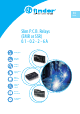
34 SERIES
Slim solid state PCB relays (SSR) 0.1- 6A
34
SERIES
Ultra-slim Solid State Relays
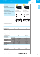
Printed circuit mount
- direct or via PCB socket
35mm rail mount
- via screw, screwless or push-in terminal
sockets
• Single circuit output switching options
- 6A, 24VDC
- 2A, 240VAC
• Silent, high speed switching with long
electrical life
• Ultra slim (5mm), package
• Sensitive DC Input circuits (Dual AC/DC input
drive possible using 93 series sockets)
• UL Listing (certain relay/socket combinations)
• Wash tight: RTIII
• 3000VAC insulation, input-output
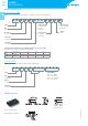
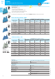
34.81.7.xxx.9024 34.81.7.xxx.8240
• 6A, 24VDC output switching
• PCB or 93 series sockets
• 2A, 240VAC output
switching
• Zero crossing switching
• PCB or 93 series sockets
input output input output
Copper side view Copper side viewFor outline drawing see page 9
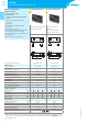
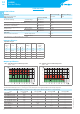
Output circuit
Contact configuration 1 NO (SPST-NO) 1 NO (SPST-NO)
Rated current/
Maximum peak current (10ms) A 6/50 2/80
Rated switching voltage V
24DC 240AC (50/60Hz)
Switching voltage range V (1.5…33)DC (12…275)AC
Maximum blocking voltage V 33 —
Repetitive peak off-state voltage V
pk
— 800
Rated load DC13 W 36 —
Rated load AC15 VA — 300
Minimum switching current mA 1 35
Max. “OFF-state” leakage current mA 0.001 1.5
Max. “ON-state” voltage drop V 0.4 1.6
Supply specification
Nominal voltage (U
N
) VDC 5 12 24 60 5 12 24 60
Rated power W 0.035 0.085 0.17 0.21 0.06 0.085 0.17 0.21
Operating range VDC
3.5…12
8…17 16…30 35…72
3.5…10
8…17 16…30 35…72
Control current mA 7 7 7 3.5 12 7 7 3.5
Release voltage VDC 4 4 10 20 1 4 10 20
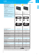
Technical data
Electrical life at rated load cycles >10
6
>10
6
Operate/release time ms 0.02/0.2 11/11
Insulation between input and output (1.2/50µs) kV
4 4
Ambient temperature range °C –20…+70* –20…+50*
Environmental protection
RT III RT III
Approvals (according to type)
* Note: all technical data relates to using the relay directly on PCB or PCB socket type 93.11.
If the relay is used with 35mm rail socket type 93.51, refer to the technical data of 38 Series; if used with types 93.60,
93.61, 93.62, 93.63, 93.64, 93.65, 93.66, 93.67,93.68 and 93.69, refer to the technical data of the MasterINTERFACE 39 Series.
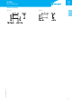
See L34 diagrams page 8