
Data Sheet


X-2017, www.findernet.com
7
A
34
SERIES
34 SERIES
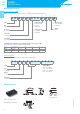
Ultra-Slim PCB relays
Electromechanical relay
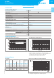
Technical data
Insulation according to EN61810-1
Nominal voltage of supply system VAC 230/400
Rated insulation voltage VAC 250 400
Pollution degree 3 2
Insulation between coil and contact set
Type of insulation Reinforced
Overvoltage category III
Rated impulse voltage kV (1.2/50μs) 6
Dielectric strength VAC 4000
Insulation between open contacts
Type of disconnection Micro-disconnection
Dielectric strength VAC/kV (1.2/50μs) 1000/1.5
Conducted disturbance immunity
Burst (5…50)ns, 5kHz, on A1 - A2 according to EN61000-4-4 level 4 (4kV)
Surge (1.2/50μs) on A1 - A2 (differential mode) according to EN61000-4-5 level 3 (2kV)
Other data
Bounce time: NO/NC ms 1/6
Vibration resistance (5…55)Hz: NO/NC g 10/5
Shock resistance g 20/14
Power lost to the environment without contact current W 0.2
with rated current W 0.5
Recommended distance
between relays mounted on PCB mm ≥5
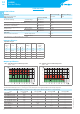
Contact specification
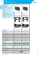
F 34 - Electrical life (AC) v contact current H 34 - Maximum DC1 breaking capacity
Cycles
Resistive load - cosφ = 1
Inductive load - cosφ = 0.4
DC breaking current (A)
DC voltage (V)
• When switching a resistive load (DC1) having voltage and current values
under the curve, an electrical life of ≥60·10
3
can be expected.
• In the case of DC13 loads, the connection of a diode in parallel with the
load will permit a similar electrical life as for a DC1 load.
Note: the release time for the load will be increased.
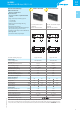
Coil specifications
DC coil data R 34 - DC coil operating range v ambient temperature
Nominal
voltage
Coil code Operating range Resistance
Rated coil
consumption
U
N
U
min
U
max
R I at U
N
V V V
Ω
mA
5 7.005 3.5 7.5 130 38.4
12 7.012 8.4 18 840 14.2
24 7.024 16.8 36 3350 7.1
48 7.048 33.6 72 12300 3.9
60 7.060 42 90 19700 3
1 - Max. permitted coil voltage.
2 - Min. pick-up voltage with coil at ambient temperature.