
User Manual

Version 1.0 Page 7
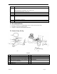
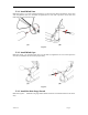
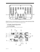
5.3.5 Install Mounting Pole
Reference Figure 6. The mounting assembly includes two U-Bolts and a bracket that tightens around
a 1 to 2” diameter pole (not included) using the four U-Bolt nuts.
(a)
(b)
Figure 6
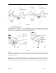
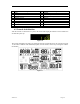
Use the bubble level next to the rain sensor to make sure the sensor array is completely level. If the
sensor array is not level, the rain gauge will not measure properly.
5.3.5.1 Aligning the Wind Direction
Locate the four wind vane compass rose indicators of N, E, S, W (representing North, East, South and
West) at the base of the wind vane. Align the compass rose direction upon final installation with a
compass or GPS.
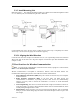
5.5 Best Practices for Wireless Communication
Note: To insure proper communication, mount the remote sensor(s) upright on a vertical surface,
such as a wall. Do not lay the sensor flat.
Wireless communication is susceptible to interference, distance, walls and metal barriers. We
recommend the following best practices for trouble free wireless communication.
1. Electro-Magnetic Interference (EMI). Keep the console several feet away from computer
monitors and TVs.
2. Radio Frequency Interference (RFI). If you have other 915 MHz devices and
communication is intermittent, try turning off these other devices for troubleshooting
purposes. You may need to relocate the transmitters or receivers to avoid intermittent
communication.
3. Line of Sight Rating. This device is rated at 300 feet line of sight (no interference, barriers or
walls) but typically you will get 100 feet maximum under most real-world installations, which
include passing through barriers or walls.
4. Metal Barriers. Radio frequency will not pass through metal barriers such as aluminum
siding. If you have metal siding, align the remote and console through a window to get a clear
line of sight.