Installer Guide
Adaptability to Enhanced Security AdapTec Plus combines power supply and door access controller features in a compact casing for an encrypted and secure I/O function, enhancing door access control functionalities and easing installation processes.
Emergency Alerts with Siren Compatible with an NC siren type with a maximum of 0.5A load for an emergency event e.g. if the terminal is being dismantled without authorization. Seamless Integration with FingerTec Terminals Mix and match the FingerTec terminals via AdapTec Plus for a cost effective access control system suitable for small and medium sized offices.
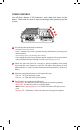
UNDERSTANDING THE DESIGN AdapTec Plus consists of 2 main modules 3 4 1 2 1 Power supply/power input module 2 Power output/access control module 1 2 3 Door lock timer 4 LED status indicator 3 4 5 6 Power supply/power input module 1 This portion is to be connected to a power source with AC110~240V. An AC current should be supplied into this side and a 12VDC 3A current will be generated as output. 2 These two cables, -V and +V are default and are connected to the inner part of AdapTec.
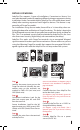
OTHER FEATURES You will find a buzzer, 4 LED indicators, and a door lock timer on the board. Check and set each of them accordingly after powering up the system. 1 2 3 4 1 You will hear the buzzer beep to indicate: • Unlocked Door (Short buzz) Door is unlocked and access granted (during verification or pressing push release button).
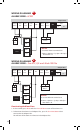
DETAILS OF WIRING AdapTec Plus supports 2 types of installations, Convenient or Secure. You can select between modes by applying different wiring arrangements during installation. Under Convenient mode, AdapTec Plus will unlock doors immediately after receiving responses from FingerTec devices. This feature is supported by all FingerTec models. For installations using Secure mode, there will be a 1s time delay when unlocking the door after verification at FingerTec devices.
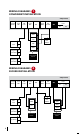
WIRING DIAGRAMS 1 Convenient Installation AdapTec Plus Tamper Siren EM +12V Siren Exit Data OV OV Mute Switch Switch Out Lock Out D1 D0 GND 12V EM + Lock __ NO Exit Button GND Emergency 3 Break Glass 2 Connection Points Emergency 2 Break Glass 3 WIRING DIAGRAMS 2 SECURE Installation AdapTec Plus Tamper Siren EM +12V Siren Exit Data OV OV Mute Switch Switch Out Lock Out D1 D0 EM + Lock __ GND 12V Exit Button GND WD1 WD0 Emergency 2 Break Glass 3 Connect
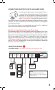
CONNECTING ADAPTEC PLUS TO AN ALARM SIREN For all FingerTec door access control models, there is a security button behind the terminal. During normal operation, the security button is compressed and once the terminal is dismantled, the button will be released and a “System broken” message will appear onscreen. During the release of the button, the terminal will output an alarm signal. However, no alarm sound will be emitted if the terminal is not equipped with an external siren.
WIRING DIAGRAMS 4 ALARM SIREN • AC900 AdapTec Plus Tamper Switch Siren Out + --Alarm Siren EM Lock +12V Out OV Siren Mute Exit Switch Data OV D1 D0 Siren Mute Button ALM + ALM ---- Connection Points Remark: • Set Auto Alarm in terminal to N. • Menu > Options > Sys Opt > Adv Opt > Auto Alarm > N.
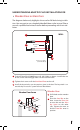
UNDERSTANDING ADAPTEC PLUS INSTALLATION FOR • Wooden Door or Glass Door The diagrams below only highlights the use of an EM lock during installation. You may opt to use a dropbolt/deadbolt/door strike instead. Please consult a qualified technician/installer before proceeding with the installation. WALL 1 2 Back Steel Plate Screws 3 4 feet / 1.2 meter (recommended) 1 To install FingerTec AC900/R2 on a wall, drill 5 holes as shown.
Glass Doorframe U-Bracket 1 Allen Key Screws Steel Bar 1 Allen Key Screws 2 Philip Screw Glass Door 1 Lodge the U-Bracket into the upper edge of the glass doorframe. Tighten the 4 Allen Key Screws to hold the U-Bracket into position. 2 Place the Steel Bar on the side of the U-Bracket. Tighten the Philip Screws to lock the Steel Bar onto position. Doorframe Screws Magnet Allen Key Screws Aluminum Plate 1 1 2 3 1 Drill 4 holes on the wooden frame.
OVERVIEW OF THE WHOLE SYSTEM INSTALLATION AC110/240V Power Input Switching power supply 12VDC 12VDC Rechargeable battery ABOVE CEILING CEILING ON-OFF Keyswitch EM Lock Emergency Break Glass Hub/Switch w 1 2 4 5 7 3 ESC 6 8 9 0 MENU OK R2 FingerTec Terminal Push Button OUTDOOR INDOOR PC NETWORKING 13
FINGERTEC ACCESSORIES For more accessories go to accessory.fingertec.com. HID Card / MiFare Card / RFID Card ON-OFF Keyswitch AdapTec Plus RFID Key Chain EM 600 / EM 1200 Alarm Siren with Strobe Light Emergency Break Glass Contactless Release Button Release Button MOUNTING AN ADAPTEC PLUS ONTO A WALL Mount the AdapTec Plus on a wall Identify a location to mount the AdapTec Plus on a wall. Fix the AdapTec Plus onto the wall by tightening the screws into the 4 holes.
NOTE: Details in this user guide are subject to change. Check http://product.fingertec.com for latest product information. © 2000-2013 FingerTec Worldwide Sdn. Bhd. All rights reserved. • Printed in Malaysia.