A COOL TEM S Y S LING C Y C NT RE BE-15/15C Service Manual lete C o mp ation m infor units for all d acture manuf 91 to 9 from 1 t ! s e r p en Version 1.
“BE SERIES” BE-15/15C SERVICE MANUAL Version 1.3 Introduction This service manual and troubleshooting guide for the BE-15/15C takes the technician through an orderly routine to determine the trouble areas and/or the cause of a problem. In many cases, damaged or defective parts are the result of failures from other components. This guide’s goal is to get to the root of a problem.
Safety Precautions WARNING: READ, UNDERSTAND, AND FOLLOW THIS SERVICE MANUAL AND THE “BE SERIES” OPERATION MANUAL COMPLETELY BEFORE INSTALLING, OPERATING, TROUBLESHOOTING, OR SERVICING A “BE” UNIT. FAILURE TO FOLLOW THESE PRECAUTIONS CAN RESULT IN SERIOUS INJURY OR DEATH. ELECTRICAL WIRING, TROUBLESHOOTING, OR REPAIRS SHOULD BE PERFORMED AND CHECKED BY A QUALIFIED ELECTRICIAN. WEAR PROPER EYE AND SKIN PROTECTION WHEN WORKING WITH THIS EQUIPMENT.
Getting Started SEQUENCE OF OPERATION: To better service a BE-Series coolant reclaimer, understanding each step of the operational sequence is necessary. Below is an outline of the operation: 1. FILL - The operator pours or pumps 15 gallons of waste antifreeze/coolant into the Process Tank through the Fill Funnel. A Level Control Probe senses the presence of liquid, activating a relay on the Level Control Board (a slight “click” will be heard). 2.
MODEL DETERMINATION: The first step is to determine the model of the unit. This depends on the type of cooling system used. There are three varietiesknowing which one you're dealing with is vital to proper troubleshooting. 1. BE-15 “Water-cooled” uses tap water (or an external cooling system) to recondense vapors. 2. BE-15C “Chiller” is the original design of BE-15C and uses a refrigeration/Freon cooling system. 3. BE-15C “Air-cooled” is the last design (and most common) and uses a fan-cooled radiator.
HISTORY OF DESIGN CHANGES: Take special note of the serial number of the unit. This number can be found on a nameplate located on the left side panel (a five digit sequence number, a letter corresponding to a month, then the year built). It is vital to know the design vintage of your “BE” unit. Older units used 120 VAC controls while later design units use 240 VAC controls. Replacement parts and voltage readings will differ between the two designs.
Maintenance Schedule MINIMUM MAINTENANCE REQUIREMENTS: Regular maintenance and upkeep is the key to preventing problems with “BE Series” equipment. Keeping the Process Tank clean is the single-most important preventive maintenance requirement. Avoid the processing of heavily contaminated used coolant and do not process coolants containing oil, transmission fluid, or gasoline. When antifreeze/coolant is spilled or splashed, clean it up immediately.
Semi-annually: HEAT EXCHANGER - Clean the finned-tube surfaces of the radiator by blowing compressed air through the fins from the inside to the outside. LEVEL PROBE - Remove the Level Control Probe (disconnect the white wire and unthread the probe with a spark-plug socket). Wipe the probe’s metal rod with a shop rag to remove any build-up of residues. Take care not to bend the rod. Reinstall the probe; making sure that the rod does not make contact with the inside of the pipe.
Storing the BE unit: PREPARE THE COOLING SYSTEM - Drain and clean the Pump Reservoir per the instructions in the “Maintenance Schedule” section of this manual. Re-fill the Pump Reservoir with a 50/50 mix of water and new antifreeze or recycled antifreeze that contains reinhibitor. This will help to protect the radiator and piping from corrosion (the antifreeze will be circulated through the cooling system during the next step). Replace the cover to the Pump Reservoir.
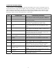
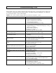
Troubleshooting Chart This troubleshooting section will list a Problem with the Possible Causes. The Possible Causes will be in the recommended order that the items should be checked. “Troubleshooting Tests and Repairs” are outlined in the “Service Procedures” section of this manual. NOTE: Some of the troubleshooting tips will not be accurate for units D91 or older. Problem Unit will not turn on. Premature Shutdown. All 11 gallons of distillate go into the Processed Water drum.
Service Procedures IMPORTANT: If performing troubleshooting procedures and an electrical component is found to be defective, it is important to find out what caused the component(s) to fail. Most electrical failures occur as a result of other defective components, power fluctuations, or a wire “grounding out”. The only wires in the entire electrical circuitry of the BE unit that should be grounded are wires #21 and #22 from the Level Control Board.
PROBLEM: UNIT WILL NOT TURN ON. Possible Cause 1: No or Improper Electrical Power. WARNING: Electrical shock hazard present. Electrical servicing should be performed by a qualified electrician. Check main circuit breaker. If tripped, verify correct wiring and electrical supply to the BE unit. F92 and newer units require a 3-wire (L1, L2, and Ground) 240 VAC, single-phase electrical supply. No neutral wire should be used or connected to the terminal strip in the BE’s circuit box.
If the LED on the Level Control Board still does not light, place a jumper wire between wire #21 and wire #22 on the Level Control Board. If the LED lights, then replace wire #21 from the Level Control Board to the Level Probe. If the LED does not light, the board is defective and must be replaced. Possible Cause 3: Safety overtemp sensor(s) activated. CAUTION: Disconnect electrical power to the BE unit before performing tests on the Temperature Actuated Switches. Check TAS2.
Possible Cause 4 & 5: On/off Switch is defective and/or Level Control Board’s relay not closing. There is a small relay mounted to the Level Control Board. The terminals for this relay’s output are located on the lower right corner of the board and labeled “NO”, “COM”, and “NC”. Whenever the board’s red LED is lit, the contacts between “NC” and “COM” should close and energize the coil on the On/off Switch. This can be checked by measuring for voltage at the On/off Switch.
PROBLEM: PREMATURE SHUTDOWN. Possible Cause 1: Electrical power outage. If power to the unit is interrupted (even for a second), the unit will shut off. The cycle can be restarted by pressing the On/off Switch ON (the unit may have to cool before it will restart). Possible Cause 2: Distillate Piping has overheated from improper cooling. CAUTION: Disconnect electrical power to the BE unit before performing tests on any of the Temperature Actuated Switches. Check TAS4 (units J91 or newer).
1. Vacuum/circulation Pump motor is not coming on. For units E91 or older, the motor is supposed to run as soon as the unit is turned on. For units F91 to E92, the motor is supposed to run after the Process Tank reaches 180 and TAS1 has closed (usually about one hour after starting the unit). Check the pump motor’s contactor in the unit’s circuit box (upper right contactor). There should be 240 volts at wires #8 and #9 when the contactor is engaged.
4. Cooling control system may be faulty (units F91 through I91). The TAS1 temperature sensor is located on the top of the Process Tank (It is a 1/2” diameter white ceramic sensor with a brass hex base and two wires #13 and #19 connected to it) is a “normally open” switch. When the tank reaches 180F, the sensor closes, energizing the coil on the Chiller/pump contactor. This allows the cooling water to flow through the Condenser. Hint: If the pump’s motor turns on, TAS1 is operating OK.
6. Vacuum/circulation Pump motor is not coming on. For units E91 to E92, check the pump motor’s contactor in the unit’s circuit box (upper right contactor). There should be 240 volts at wires #8 and #9 when the contactor is engaged. If the contactor is not engaged, verify there is 120 volts to the coil (wires #18 and #19). If so, the coil is defective, and the contactor needs replaced. If the pump motor’s contactor is functioning, determine whether the pump motor is defective.
1. Improper maintenance. If the Process Tank is not drained after every run and the Residues are slow to drain, most likely there is a Residue build-up. Proper maintenance is the key to preventing a buildup in the Process Tank. 2. Large concentrations of solids in the waste coolant or in the Residue during a Residue Run. 3. Oil or transmission fluid is present in the waste coolant. When this is the case, the residue is less likely to be flushed away with the “Flush” procedure during maintenance.
PROBLEM: ALL 11 GALLONS OF DISTILLATE GO INTO THE PROCESSED WATER DRUM. Possible Cause 1 & 2: Loose wire on TAS3 or TAS3 is defective or Stuck/faulty Divert Solenoid Valve. CAUTION: Disconnect electrical power to the BE unit before performing tests on the Temperature Actuated Switches. Check the wire connections on TAS3.
PROBLEM: ALL 11 GALLONS OF DISTILLATE GO INTO THE RECYCLED GLYCOL DRUM. Possible Cause 1 & 2: Wires/terminals on TAS3 are touching or TAS3 is defective or Stuck/faulty Divert Solenoid Valve. CAUTION: Disconnect electrical power to the BE unit before performing tests on the Temperature Actuated Switches. The first sign that this is going to occur is if the unit “belches” when pouring waste coolant into the Fill Funnel. Also, the Vacuum Gage will begin to show vacuum on as soon as the unit is turned on.
PROBLEM: LESS THAN 3 1/2 GALLONS OF RESIDUE DRAINS AFTER PROCESSING. Possible Cause 1: Clogged Drain Valve. CAUTION: Do not open the fill valve or drain valve during operation or while hot. Allow a minimum of one-half to two hours for cooling before draining or refilling. CAUTION: Wear proper eye and skin protection when working with this equipment. Check for Residue or debris blocking the Drain Valve. This can occur if there were solids or sediment poured into the Fill Funnel with the waste coolant.
If the LED goes out, then the probe itself is making contact to ground. This can be confirmed by checking continuity between the terminal on the top of the probe and the pipe. If there is continuity, remove the probe from the pipe, and thoroughly clean the probe and the inside of the pipe. Residue build-up can form a “bridge” between the probe and the pipe. Check whether the probe is straight. If the probe is slightly bent, it may touch the side of the pipe.
PROBLEM: UNIT KEEPS RUNNING AFTER THE ON/OFF SWITCH IS OFF. WARNING: Electrical shock hazard present. Electrical servicing should be performed by a qualified electrician. Possible Cause 1: Improper electrical hook-up. Verify that the power supply leads are correct from the main circuit. If the colors of the wire leads are misinterpreted, “hot” leads or “neutral” leads can be connected incorrectly causing power to be fed back through the electrical system of the unit.
PROBLEM: UNIT RUNS LONGER THAN 24 HOURS WITH NOTHING OR LITTLE PRODUCED. WARNING: Electrical shock hazard present. Electrical servicing should be performed by a qualified electrician. Possible Cause 1: Contactor not engaging or defective. Determine whether the Heater Band’s Contactor has engaged. While the BE unit is turned on, check for voltage to the Contactor’s coil (wires #13 and #18). If there is proper voltage between these two wire and the contactor has not engaged, the Contactor should be replaced.
PROBLEM: CIRCUIT BREAKER AT POWER MAIN KEEPS TRIPPING. Possible Cause 1: Wiring short to ground. Check all wires for continuity to ground. CAUTION: Disconnect electrical power to the BE unit before performing continuity tests on the circuitry of the BE unit. Systematically, check every wire connection for continuity to ground. The majority of the wires are terminated in the circuit box inside the unit. Also check the wires on the On/off switch and all TAS’s.
PROBLEM: LOW VACUUM READINGS AFTER DIVERT (LESS THAN -24” Hg.) Possible Cause 1: Pump Reservoir is low. Check whether the Pump Reservoir is low on fluid. This is the most common cause. The reservoir only needs to be about 1/2” low to diminish coolant flow through the Aspirator. Top off the reservoir with water or Recycled Glycol until it overflows from the Recycled Glycol Hose. Possible Cause 2: Vacuum hose leaking or deteriorated. Two hoses are subjected to the vacuum generated by the Circulation Pump.
Possible Cause 5: Stuck/faulty Divert Solenoid Valve. Determine whether the Divert Valve is stuck between two positions. During normal operation, the Distillate Piping is open and at atmospheric pressure during the water process. Once the glycol process begins, the Divert Valve switches positions to allow the Distillate Piping and the Process Tank to be under up to -28” Hg. of vacuum.
PROBLEM: PRESSURE RELIEF VALVE KEEPS DISCHARGING. Possible Cause 1: Stuck/faulty Divert Solenoid Valve. Determine whether the Divert Valve is stuck between two positions. During normal operation, the Distillate Piping is open and at atmospheric pressure during the water process. Once the glycol process begins, the Divert Valve switches positions to allow the Distillate Piping and the Process Tank to be under up to -28” Hg. of vacuum.
PROBLEM: DISCOLORED RECYCLED GLYCOL. Possible Cause 1: No problem. This can be normal. Recycled Glycol from a BE unit will have a variety of tints—colorless to green, blue, amber, red, or brown. This can be completely normal and will have no adverse effect on the performance of the finished product once properly reinhibited. Possible Cause 2: Oil in Waste Coolant feed. Recycled Glycol that is dark brown with a film floating on the top (and a foul odor) is due to excessive oil in the Waste Coolant feed.
LEVEL CONTROL BOARD REPLACEMENT: CAUTION: Disconnect electrical power to the BE unit before replacing the Level Control Board. When replacing a Level Control Board take care to install the proper wires onto the proper terminals. If any of the wire’s push-on connectors seem loose or corroded, replace the connectors as well.
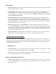
DIVERT VALVE REPAIR OR REPLACEMENT: CAUTION: Disconnect electrical power to the BE unit before repairing or replacing the Divert Solenoid Valve. Repairing the Divert Valve: 1. Find the Divert Valve in the piping of the unit. It is brass in color and has a large hex nut on one side. If you are agile enough, you may be able to reach the Divert Valve through the access hole in the top panel of the BE unit or from underneath the front opening. Otherwise, remove the top panel from the unit.
CLIP SOLENOID COIL STEM ASSEMBLY SPRING SEAT PLUNGER ASSEMBLY PINS VALVE BODY DISC DISC SPRING HEX CAP DIVERT SOLENOID VALVE EXPLODED VIEW 33
Replacing the Divert Valve: 1. Find the Divert Valve in the piping of the unit. It is brass in color and has a large hex nut on one side. If you are agile enough, you may be able to reach the Divert Valve through the access hole in the top panel of the BE unit or from underneath the front opening. Otherwise, remove the top panel from the unit. Be careful—there are four wires and a hose attached. Set the top on its right side on top of a crate or other support near the right front corner of the unit. 2.
HEATER BAND REPLACEMENT: Parts Required: Quantity 1 1 1 Part Number J101104 J101499 J102319 Description Heater Band Heater Band Strap, upper Heater Band Strap, lower with loop Procedure: CAUTION: Disconnect electrical power to the BE unit before working with or replacing the Heater Band. 1. Drain all liquid from the processing tank. Remove the front panel and top panel of the BE unit and set aside. Be careful—there are four wires and a hose attached to the top panel.
9. Position the Ceramic Terminal Caps over the studs on the Heater Band and reconnect the electrical wires (it is not critical which wire goes on which stud). Make sure the connections are good and tight. IMPORTANT: It is critical that the metal bands NEVER make contact with the electrical terminals during operation of the BE unit. 10.
HEATER BAND INSULATION BOTTOM OUTSIDE INSULATION TANK INSULATION WELD SEAM PROCESS TANK PLASTIC SKIN WIRES #6 AND #7 HEATER BAND DETAIL OF PROCESS TANK AND HEATER BAND LOWER STRAP (WITH LOOP) STRAP BOLTS UPPER STRAP
VACUUM/CIRCULATION PUMP SERVICING: The Vacuum/circulation Pump is located on top of the Pump Reservoir. This centrifugal-type pump is powered by a close-coupled TEFC electric motor rated at 1/2 hp, 3450 rpm, 230 volt, 1 phase, 60 hertz. The motor is wired for clock-wise rotation when facing the motor’s fan. CAUTION: Disconnect electrical power to the BE unit before working on or repairing the Vacuum/circulation Pump and motor. Pump and motor removal and re-installation: 1.
Pump and motor disassembly: 1. Set the pump and motor assembly onto the motor fan cover so that the pump is facing upright on the workbench. 2. Remove the five socket-head bolts that hold on the pump’s housing and remove the pump housing. The nuts for the bolts are recessed into the tabs of the motor adapter. Also remove the housing o-ring. IMPORTANT: Take note of the orientation of the pump’s discharge (where the elbow is attached) to allow proper reassembly after repairs. 3.
PUMP HOUSING IMPELLER HOUSING COVER SEAL SET SCREWS MOTOR ADAPTOR MOTOR MOUNTING PLATE MOTOR PUMP DISCHARGE ELBOW ASPIRATOR .020" +/-.
Location Diagrams and Parts Lists This section provides a comprehensive list of most replaceable parts on a BE unit. Since this model has been discontinued in the year 2000 some replacement part are no longer available (see notes in parts list). The index below will pinpoint the proper parts list or parts location diagram. Many of the parts are illustrated and labeled to assist in the parts selection. It is critical to consult the proper “serial-number-sensitive” chart for any replacement parts ordered.
BOTTOM OUTSIDE INSULATION HEATER INSULATION TANK GROUND TAS2 TAS3 FILL VALVE FILL FUNNEL HEATER BAND DRAIN VALVE LEVEL CONTROL PROBE PROCESS TANK TANK INSULATION TOP TANK INSULATION PRESSURE RELIEF VALVE SIDE PLASTIC SKIN BE-15/15C PARTS CUTAWAY TOP PLASTIC SKIN FAN/MOTOR RADIATOR CIRCUIT BOX RECYCLED GLYCOL HOSE PUMP RESERVOIR TAS4 PUMP MOTOR DIVERT SOLENOID VALVE TO VACUUM GAGE CONDENSER
CIRCUIT BOX/ELECTRICAL COMPONENTS: 120 VOLT UNITS E91 THRU E92 TEMPERATURE ACTUATED SWITCH (TAS) LEVEL CONTROL BOARD TERMINAL STRIP ON/OFF SWITCH CONTACTORS
CIRCUIT BOX/ELECTRICAL COMPONENTS: 240 VOLT UNITS F92 OR NEWER TEMPERATURE ACTUATED SWITCH (TAS) LEVEL CONTROL BOARD ON/OFF SWITCH TERMINAL STRIP CONTACTOR
DIVERT VALVE TO PROCESSED WATER HOSE FROM PROCESS TANK VACUUM HOSE RECYCLED GLYCOL HOSE CONDENSER WATER SOLENOID VALVE WATER IN WATER OUT COOLING COIL PUMP RESERVOIR ASPIRATOR ELBOW BE-15 "WATER-COOLED" DISTILLATE PIPING AND HOSE LAYOUT DIVERT VALVE TO PROCESSED WATER HOSE VACUUM HOSE FROM PROCESS TANK CONDENSER RETURN FROM RADIATOR PUMP RESERVOIR RADIATOR OUT RADIATOR IN RECYCLED GLYCOL HOSE ELBOW ASPIRATOR BE-15C "AIR-COOLED" DISTILLATE PIPING AND HOSE LAYOUT 45
BE-15/15C PARTS LIST: UNITS A91 THRU E92 Part # M100860 J101135 J100634 J101108 A101104 M100864 J101114 J101885 A101179 J101558 J101300 J101721 J101104 J101498 J102319 J101499 A101103 M100991 M100988 M100987 M100990 J101130 J101129 J101105 J101140 M100985 M100986 J101111 J101210 J102467 J101131 J101621 J101119 J102149 J101139 J100212 M100959 J101514 M101626 M100862 J102774 A101678 M100958 J101444 J101256 A101193 A101109 Description Notes Aspirator Barbed Hose Fitting Condenser Contactor Cooling Coil Cool
BE-15/15C PARTS LIST: UNITS F92 AND NEWER Part # M100860 J101135 J100634 J101486 A101104 M100864 J101892 J101885 A101179 J101558 J101300 J101721 J101104 J101498 J102319 J101499 A101103 M100991 M100988 M100987 M100990 J101888 J101129 M100968 J101890 J101140 M100985 M100986 J101111 J101210 J102467 J101131 J101621 J101119 J102149 J101668 M100943 J100212 M100959 J101514 M101626 M100862 J102774 A101678 M100958 J101444 J101256 A101193 A101109 Description Notes Aspirator Barbed Hose Fitting Condenser Contactor
Electrical Schematics The schematics of the electrical components and wiring are presented in a ladder configuration. The proper schematic for a particular BE unit is dependent upon its serial number.
GND L1 L2 N CR1-2 CR1-1 10 10 C2-1 C1-1 6 5 TAS 350 S1 4 ON/OFF SWITCH 11 PB1 BE-15/15C ELECTRICAL SCHEMATIC UNITS D91 AND OLDER 1 1 1 1 1 W MTR1 CHILLER (if equipped) HEATER 4 11 13 13 13 R CR1 9 TAS3 TAS2 7 C2 14 C1 12 C2-2 C1-2 * 3 3 3 SOL2 * 3 3 3 3 MOST UNITS RETROFITTED WITH SERIES 16 LEVEL CONTROL BOARD.
GND L1 L2 N 8 6 25 TAS4 G L1 L H L2 N.O. COM MTR1 24 10 HEATER N.C.
GND L1 L2 N 8 6 25 TAS4 TO TANK GROUND C2-1 C1-1 G L1 L H L2 N.O. COM MTR1 MTR2 10 24 HEATER N.C.
GND L1 L2 25 8 6 TAS4 10 TO PROBE C1-2 C1-1 L L C O L1 G L2 N.O. COM. MTR1 26 7 9 TAS3 13 13 22 TAS1 TO TANK GROUND HEATER N.C.
GND L1 L2 25 8 6 TAS4 10 TO PROBE C1-2 C1-1 G L L C O N.O. COM. N.C.
Notes Finish Thompson Inc. 921 Greengarden Road Erie, PA 16501-1591 USA Ph. 814-455-4478 Fax 814-455-8518 Technical Service Hotline 800-888-3743 or Email: techservice@finishthompson.