COOLANT RECYCLING SYSTEM BE-55C Instruction Manual For units Serial # number 0660A96 or newer Version 7 July 2014
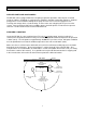
BE-55C Instruction Manual ~ Introduction ~ Congratulations on your purchase of the BE-55C Coolant Recycling System. The BE-55C is designed to recycle used ethylene or propylene glycol-based engine coolants utilizing vacuum distillation technology (the same process used in the manufacture of new anti-freeze). The recycled product meets or exceeds original equipment specifications. The process is completely automatic, requiring minimal operator involvement.
~ Safety Precautions ~ WARNING: READ THIS MANUAL COMPLETELY BEFORE INSTALLING AND OPERATING THIS UNIT. FAILURE TO FOLLOW THESE PRECAUTIONS CAN RESULT IN SERIOUS INJURY OR DEATH. A QUALIFIED ELECTRICIAN SHOULD PERFORM ELECTRICAL WIRING. WEAR PROPER EYE AND SKIN PROTECTION WHEN OPERATING THIS EQUIPMENT. DO NOT OPEN THE FILL VALVE OR DRAIN VALVE WHILE THE UNIT IS PROCESSING. ALLOW A MINIMUM OF TWO HOURS TO COOL BEFORE DRAINING OR RE-FILLING. WARNING: PROCESS GLYCOL-BASED ENGINE COOLANTS ONLY.
~ Part Descriptions and Terminology ~ Antifreeze - A cooling medium base composed of ethylene glycol or propylene glycol, corrosion inhibitors and other additives, and dye. Aspirator - An internally tapered, plastic tubular attachment to the Vacuum/circulation pump used to create Vacuum. Condenser - A shell and tube heat exchanger. The vapors pass through the tubes as cooling water circulates through the shell to recondense the vapors into a purified liquid. Part of the Distillate Piping.
~ Installation & Start-up ~ SUPPLIED PARTS AND ACCESSORIES: The BE-55C comes equipped with most everything required for operation. A box of parts is located inside the cabinet. Reinhibitor is required and is available in 5-gallon or 55-gallon containers. Optional pump primer is also available to initially fill the pump reservoir. The user must supply their own receiving and storage drums, electrical wiring, air hose to the unit, and piping for the pressure relief system.
FILL & DRAIN ASSEMBLY: Remove the plugs from the Fill Port and the Drain Port on the left side of the BE-55C. Assemble and install the Fill Pipe Assembly onto the Fill Port and the Drain Pipe Assembly onto the Drain Port. The Drain Pipe Assembly consists of two parts. Thread the part with the tee onto the nipple of the drain port, and the second part (with the flare fitting) into the top of the tee. Turn the parts as necessary to allow the valves to operate freely.
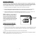
ELECTRICAL CONNECTIONS: The BE-55C requires a 208-240 volt, 3 phase, 60 Hz (special 50 Hz units are available) and 40-amp electrical service with ground. Process times are longer at voltages less than 240V (up to 25% longer when incoming voltage is 208V). Electrical connections should be performed by a qualified electrician and in accordance with local codes. A minimum of 10 gauge copper wire must be used. 1. Remove the front panel of the BE-55C. Remove the cover from the circuit box. 2.
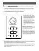
~ Sequence of Operation ~ The BE-55C requires minimal operator involvement. Once the unit is filled with waste coolant and started, the unit can operate virtually unattended until the process is complete. Following is the normal sequence of operation for a waste coolant run in the BE-55C. FILL - The Fill Hose is inserted into a 55-gallon waste coolant drum. A Fill Switch on the BE-55C starts a vacuum pump. As a vacuum is formed in the process tank, the Fill Valve is opened to draw in the waste coolant.
~ Operating the BE-55C ~ CAUTION: ALWAYS WEAR SAFETY GOGGLES, PROTECTIVE CLOTHING, AND GLOVES WHEN OPERATING THIS UNIT. 1. Position your two collection drums to the right of the BE-55C and insert the unit’s hoses into the drums. Take care to not allow the level of the processed liquid to cover these hoses to prevent over-pressure or liquid from being drawn back into the process tank. 2. Insert the clear, braided Fill Hose into your waste coolant drum. 3. Close both the Fill Valve and the Drain Valve. 4.
6. The Processed Water and Processed Glycol are now ready for mixing and reinhibiting (refer to the Adding Reinhibitors/Freeze Point Check instructions at the end of the manual). The Processed Glycol normally contains approximately 10-20% water. 7. Allow the BE-55C to cool for at least two to three hours. NOTE: Warm residues flow easier than cold residues, allowing the tank to be more completely drained of residue. 8. Use the Drain Assist to remove the residues from the process tank to a waste container.
Finish Thompson Premium Inhibitor Blending Instructions Finish Thompson’s Premium Inhibitor is a fully formulated antifreeze inhibitor package designed to restore critical corrosion protection agents to glycol recycled with BE Series distillation systems. When properly inhibited, the recycled glycol meets and exceeds various performance specifications including ASTM D-3306, D-4985, D-6210 and TMC RP-329. This one part formula is easy to use and economical.
~ Maintenance Schedule ~ CAUTION: ALWAYS WEAR SAFETY GOGGLES, PROTECTIVE CLOTHING, AND GLOVES WHEN WORKING ON OR WITH THIS UNIT. CAUTION: NEVER WORK ON OR WITH THIS UNIT WHILE IT IS HOT. ALLOW A MINIMUM OF TWO HOURS COOL-DOWN TIME. EVERY CYCLE: DRAIN RESIDUES - Evacuate all residues from the process tank before attempting a waste coolant run. If less than 5 gallons of residue drains, perform a cleaning cycle (see “FLUSH” procedure in the “Weekly” section of the “Maintenance Schedule”).
BI-MONTHLY: HEAT EXCHANGERS (radiators) - Clean the finned-tube surfaces of the heat exchangers by carefully blowing compressed air through the fins from the outside to the inside. Be careful not to allow the compressed air to bend the fins. Use a shopvac on the inside to help collect the dust. ANNUALLY: PUMP RESERVOIR - Drain and clean the Pump Reservoir. On the bottom of the Pump Reservoir is a drain valve and drain hose.
Storing the BE unit: PREPARE THE COOLING SYSTEM - Drain and clean the Pump Reservoir per the instructions in the “Maintenance Schedule” section of this manual. Re-fill the Pump Reservoir with a 50/50 mix of water and new antifreeze or recycled antifreeze that contains reinhibitor. This will help to protect the radiator and piping from corrosion (the antifreeze will be circulated through the cooling system during the next step). Replace the cover to the Pump Reservoir.
~ Troubleshooting ~ The following are a few tips for diagnosing some problems you may experience during the use of your BE-55C. If the following suggestions do not pinpoint the cause of your problem, contact FTI’s toll-free “Service Hotline” from 8 a.m. to 5 p.m. EST. 1-800-888-3743 CAUTION: ALWAYS WEAR SAFETY GOGGLES, PROTECTIVE CLOTHING, AND GLOVES WHEN WORKING ON OR WITH THIS UNIT. CAUTION: NEVER WORK ON OR WITH THIS UNIT WHILE IT IS HOT. ALLOW A MINIMUM OF TWO HOURS COOL-DOWN TIME.
PROBLEM: UNIT WILL NOT TURN ON. Possible Cause 1: No or Improper Electrical Power. No power to the unit, check main circuit breaker. If tripped, verify correct wiring and electrical supply to the BE unit (see pg. 6 for electrical connections). Verify that the LED on the phase control relay is illuminated. If not, interchange any two of the three phase wires. Unit has not cooled down sufficiently from the previous batch. Allow unit to cool.
Possible Cause 3: Low Level control system not satisfied. Insufficient liquid level in Process Tank. Verify that the Process tank has been filled (minimum 8-gallons). Check the red LED on the Low Level Control Board (located in the upper left corner of the BE’s circuit box, this will be the second board). When liquid touches the Level Probe, it grounds the probe and lights the LED on the Level Control Board. If the LED is lit, proceed to Possible Cause 4.
PROBLEM: CIRCUIT BREAKER AT POWER MAIN KEEPS TRIPPING Possible Cause 1: Wiring short to ground Check all wires for continuity to ground. CAUTION: Disconnect electrical power to the BE unit before performing continuity tests on the circuitry of the BE unit. Systematically, check every wire connection for continuity to ground. The majority of the wires are terminated in the circuit box inside the unit. Also check the wires on the On/Off switch and all TAS’s.
Possible Cause 5: Stuck/Faulty Divert Solenoid Valve. Determine whether the Divert Valve is stuck between two positions. During normal operation, the Distillate Piping is open and at atmospheric pressure during the process. Once the fill process begins, the Divert Valve switches positions to allow the Distillate Piping and the Process Tank to be under vacuum.
Possible Cause 3: Debris in Aspirator Check for foreign matter logged in the Aspirator. The Aspirator is a 2” diameter plastic “tube” attached to the Circulation Pump’s elbow. Restriction of liquid or airflow will cause low vacuum. 1. 2. 3. 4. 5. Drain the Pump Reservoir of all liquid through the petcock on the bottom of the reservoir. Tilt the pump’s motor to the side to expose the Circulation Pump and the Aspirator. Remove the hose that is attached to a barbed hose fitting on the Aspirator.
CAUTION: Disconnect electrical power to the BE unit before performing tests on the temperature activated Switches (TAS) Check TAS3. This is a “normally open” switch threaded into the front of the Process Tank behind the access panel in the insulation. It is a 1/2” diameter white ceramic sensor with a brass hex base and two wires (#13 and #14) connected to it; it will be the switch on the left hand side.
Possible Cause 5: Intermittent ground on Process Tank. Verify that there is more than 7-8 gallons of liquid in the Process Tank and check the red LED on the Low Level Control Board (located in the upper left corner, second level control board in the BE’s circuit box). If the LED is not lit, check the Process Tank’s ground wire connection. This wire is attached to the Process Tank with a screw (behind the small access panel in the tank’s insulation).
TAS4 is a switch rated for 180ºF. This will be indicated by “L180” written on the sensor. The sensor should reset at 100ºF. If TAS4 has tripped, this indicates that the Distillate Piping has overheated. This can occur if the operator attempts to fill the Process Tank when the BE unit is still hot. The uncooled steam created can trip TAS4, preventing the unit from turning on. If the unit is cool, TAS4 should have reset, if not, TAS4 is defective and must be replaced.
Possible Cause 3: Residue build-up in Process Tank If proper maintenance procedures are not strictly adhered to, a build-up of residues can accumulate inside of the process tank. As the residue bakes to the sides and bottom of the tank, it can breakdown and smoke from the heat, causing discoloration and a foul odor to the recycled products. This build-up will eventually cause improper operation of the unit and ultimately damage the heater.
1. Place a jumper wire between wires #13 and #14. Verify that no wires are touching any metal parts. 2. Restore power to the unit. After about 6 seconds you should hear a click. Depress the Process Switch (with the TAS3 jumper installed). Wait approximately 10 minutes. 3. Watch the Vacuum Gage. If the unit begins to show vacuum, see how high it goes. It should reach –19”Hg to 24”Hg. If it does, replace TAS3. If no vacuum forms, the Divert Solenoid Valve is stuck in the water position.
Possible Cause 3: Clogged Drain Valve Check for residues or debris blocking the drain valve. This can occur if there were solids or sediment sucked into the unit with the waste coolant. This can also occur if residue is processed more than once (which is not recommended) or if residues are continuously remixed into the waste coolant. 1. Place a drain pan (capable of handling hot liquids) under the drain valve and open the valve.
Possible Cause 5: Low Level Control Board Failure Caution: Disconnect electrical power to the BE unit before performing tests on the Low Level Control Board. If the Low Level Control Board is defective or a false ground has occurred, the unit will continue running after the waste coolant drops below the recommended low level. This will allow the unit to continue heating until all or most of the liquid has evaporated.
Possible Cause 2: Debris, weak or improper Pressure Relief Valve. If foreign matter or debris accumulates inside the seat area of the Pressure Relief Valve the valve may become too sensitive. Further, after time, continuous exposure to vapors from exceptionally acidic Waste Coolant vapors can degrade and corrode metal parts in the valve, thereby weakening it. Remove and inspect the Pressure Relief Valve and look for any signs of debris or corrosion. Attempt to clean the internals of the valve and reinstall.
3. At the base of the Divert Valve’s stem, there will be a large hex nut. Loosen this nut, and carefully remove the stem. Be careful—there will be a plunger assembly (with spring), and a plastic spring seat inside the stem. 4. Most likely the plastic spring seat has melted. Remove the plastic spring seat—the Divert Valve can work without it. Also, clean the rest of the inside of the Divert Valve. There will be two small metal rods in the valve’s body. Clean them and make sure they move freely.
CLIP SOLENOID COIL STEM ASSEMBLY SPRING SEAT PLUNGER ASSEMBLY PINS VALVE BODY DISC DISC SPRING HEX CAP DIVERT SOLENOID VALVE EXPLODED VIEW 29
Replacing the Divert Valve: 1. Find the Divert Valve in the piping of the unit. It is brass in color and has a large hex nut on one side. If you are agile enough, you may be able to reach the Divert Valve through the access hole in the top panel of the BE unit or from underneath the front opening. Otherwise, remove the top panel from the unit. Be careful—there are four wires and a hose attached. Set the top on its right side on top of a crate or other support near the right front corner of the unit. 2.
VACUUM/CIRCULATION PUMP SERVICING: The Vacuum/circulation Pump is located on top of the Pump Reservoir. This centrifugal-type pump is powered by a close-coupled TEFC electric motor rated at 1/2 hp, 3450 rpm, 230 volt, 3 phase, 60 hertz. The motor is wired for clock-wise rotation when facing the motor’s fan. CAUTION: Disconnect electrical power to the BE unit before working on or repairing the Vacuum/circulation Pump and motor. PUMP AND MOTOR REMOVAL AND RE-INSTALLATION: 1.
PUMP AND MOTOR DISASSEMBLY: 1. Set the pump and motor assembly onto the motor fan cover so that the pump is facing upright on the workbench. 2. Remove the five socket-head bolts that hold on the pump’s housing and remove the pump housing. The nuts for the bolts are recessed into the tabs of the motor adapter. Also remove the housing oring. IMPORTANT: Take note of the orientation of the pump’s discharge (where the elbow is attached) to allow proper reassembly after repairs. 3.
33 PUMP HOUSING IMPELLER HOUSING COVER SEAL SET SCREWS MOTOR ADAPTOR MOTOR MOUNTING PLATE MOTOR PUMP DISCHARGE ELBOW ASPIRATOR .020" +/-.
BE-55C Heater Replacement/Tank Access: Units with serial number 04532I94 to current WARNING: Electrical wiring, troubleshooting and repairs should be performed by a qualified electrician. Drain residues and flush with clean water. Allow unit to cool before attempting repair or accessing tank interior. Disconnect electrical power to the unit before performing these procedures. 1. Remove three screws from the right side of the door located on the front of the unit and open the door. 2.
~ Appendix ~ SPECIFICATIONS: MODEL: BE-55C DIMENSIONS: SHIPPING WEIGHT: ELECTRICAL REQUIREMENTS: POWER CONSUMPTION: PROCESS TIME: NORMAL YIELDS: 48” wide x 30” deep x 63” tall 600 lb 208-240 VAC / 3 phase / 60 hertz / 40 amps 12.8 kilowatts during atmospheric portion of process 6.
~ BE-55C PARTS LOCATION DIAGRAM ~ 36
~ BE-55C HOSE LAYOUT DIAGRAM ~ 37 I.D.
~ BE-55C ELECTRICAL SCHEMATIC ~ 38
~ Warranty ~ CHEMICAL REACTION DISCLAIMER The user must exercise primary responsibility in selecting the product's material of construction, which are compatible with the fluid(s) that come(s) in contact with the product. The user may consult Finish Thompson, Inc. (manufacturer) and a manufacturer's representative/distributor agent to seek a recommendation of the product's material of construction that offers the optimum available chemical compatibility.