
User Manual

5
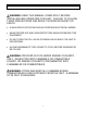
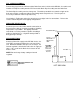
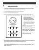
FILL & DRAIN ASSEMBLY:
Remove the plugs from the Fill Port and the Drain Port on the left side of the BE-55C. Assemble and
install the Fill Pipe Assembly onto the Fill Port and the Drain Pipe Assembly onto the Drain Port.
The Drain Pipe Assembly consists of two parts. Thread the part with the tee onto the nipple of the
drain port, and the second part (with the flare fitting) into the top of the tee. Turn the parts as
necessary to allow the valves to operate freely.
Use plumber’s Teflon tape and a pipe wrench to ensure tight, leak-free connections. Refer to the
“Parts Location Diagram” for the piping configurations.
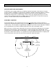
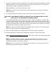
PRESSURE RELIEF VALVE:
Screw the pressure relief valve onto the connection on
the back of the cabinet. Use piping capable of handling
temperatures up to 400F. This piping should be
routed into a receiving container capable of holding 5
gallons of hot liquid (e.g., a 5 gallon metal pail with a
bung opening in the lid).
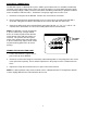
AIR CONNECTIONS:
Connect a filtered air supply to the BE-55C via the 1/4-
inch FNPT connector located on the rear panel of the
unit. Maximum allowable inlet pressure is 125 psi. An
internal regulator is installed to reduce the air supply to
10 psi. Air is used for the Drain Assist feature for the
Process Tank.
NOTE: Do not change factory setting on internal
regulator.
LEFT SIDE VIEW
INSTALL
PRESSURE
RELIEF VALVE
HERE
AIR CONNECTION
DRAIN
PORT
FILL PORT
CUSTOMER
SUPPLIED
PIPING AND
BUCKET
CUSTOMER
SUPPLIED
1”NPT x 3 1/2’
PIPING AND
5-GALLON
BUCKET
BE-55C Installation and
O
p
eration