PF SERIES PUMPS PFS OPERATION & PARTS MANUAL For Serial Number 162858 & lower
EU Declaration of Conformity Finish Thompson Inc. hereby declares that the following machine(s) fully comply with the applicable health and safety requirements as specified be the EC Directives listed. The product may not be taken into service until it has been established that the drive motor for the Drum and Container Pump complies with the provisions of all relevant EC Directives.
Introduction This manual pertains to the PF Series, specifically the PFS stainless steel drum pump. Finish Thompson Inc. thanks you for choosing our products. We believe the use of our products will be fully satisfactory. When properly installed and operated, your Finish Thompson motor and pump will provide long, trouble-free service; therefore, please read this manual carefully before carrying out any operations on the pump/motor unit.
Warranty, General Terms & Conditions 1. The following terms and conditions apply to the sale of machinery, components and related services and products, of Finish Thompson Inc. (hereinafter “the products”) 2. Finish Thompson Inc. (the manufacturer) warrants only that: a) its products are free of defects in material, design and workmanship at the time of original purchase; b) c) its products will function in accordance with Finish Thompson Inc. operation manuals; Finish Thompson Inc.
Safety 1. Introduction This manual contains all the information needed for the correct installation, use and maintenance of your new Finish Thompson pump. It should be read and understood by all the personnel involved in installation, operating and servicing of the pump before it is started. 2. Operator Qualification and Training The personnel in charge of the installation, the operation, and the maintenance of the pump must be qualified and able to perform the operations described in this manual.
Installation & Maintenance Instructions Installation 1. Remove the drum pump and motor from its packaging and inspect for shipping damage. 2. Turn the pump coupling to verify there is no binding. Verify the housing cover (item 16) is on tight (it has a left hand thread. 3. Adjust the coupling so that the empty slots in the insert are at 3 and 9 o’clock with the pump discharge at 12 o’clock. 4. Install the motor according to instructions in the appropriate motor manual. 5. Attach 1” i.d.
Reassembly 1. Install new lip seal (item 4) into the pump head with the grooved side facing the bottom of the pump. 2. If bearing assembly is replaced -- thread the shaft (item 14) into the bearing assembly (item 3) with the 3/32 hole in the shaft on the other end. Carefully insert the shaft straight through the lip seal (to avoid seal damage) from the top and seat the bearing assembly (item 3) into the pump head. 3. If o-rings are replaced -- install 2 inner tube o-rings (item 8) in the grooves.
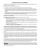
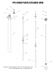
PFS SPARE PARTS EXPLODED VIEW Not Pictured: Item 25 (Middle Inner Tube - 60” & 72” pump lengths only) & Item 26 (Lower Middle Inner Tube - 72” pump length only) 6
PUMP SPARE PARTS LIST (for serial numbers 162858 and lower) ITEM 1 2 3* 4* QTY 1 1 1 1 6 1 7 1 8 1 10* 2 11 1 12* 1 13* 1 14* 1 15 1 16* 1 17 1 18† 1 19 1 20* 1 DESCRIPTION PART NUMBER COUPLING INSERT J100014 COUPLING HALF J100012 BEARING ASSEMBLY A101110 VAPOR SEAL M100008 LOCK WASHER #8 BRASS SCREW #8-32 X 1/4 BRASS PAN HEAD INTAKE TUBE ASSEMBLY 27” MODELS 40” MODELS 48” MODELS 60” MODELS 72” MODELS INNER TUBE O-RING FKM EPDM PERLAST STAINLESS STEEL UPPER INNER TUBE 27” MOD
21† 1 25 26 1 PFS HOUSING COVER (sold as a kit with Item 18) See Item 18 UPPER MIDDLE INNER TUBE 27” MODELS 40” MODELS 48” MODELS 60” MODELS 72” MODELS LOWER MIDDLE INNER TUBE 72” MODELS N/A N/A N/A M100789-3 M100789-3 M100789-1 *Recommended Spare Parts † If replacing either item number 18 or 21, you must order both to assure proper fit. Note: Bearing assembly and vapor seal can be purchased as a kit using part number 106567. Rev.