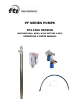
PF SERIES PUMPS PFS ATEX VERSION (INCLUDES M6A, M6XA, M10X MOTORS & SPK) OPERATION & PARTS MANUAL
Introduction This manual pertains to the PF Series, specifically the ATEX version of the PFS stainless steel drum pump. Finish Thompson Inc. thanks you for choosing our products. We believe the use of our products will be fully satisfactory. When properly installed and operated, your Finish Thompson motor and pump will provide long, trouble-free service; therefore, please read this manual carefully before carrying out any operations on the pump/motor unit.
Warranty, General Terms & Conditions 1. The following terms and conditions apply to the sale of machinery, components and related services and products, of Finish Thompson Inc. (hereinafter “the products”) 2. Finish Thompson Inc. (the manufacturer) warrants only that: a) its products are free of defects in material, design and workmanship at the time of original purchase; b) its products will function in accordance with Finish Thompson Inc. operation manuals; Finish Thompson Inc.
Safety 1. Introduction This manual contains all the information needed for the correct installation, use and maintenance of your new Finish Thompson pump. It should be read and understood by all the personnel involved in installation, operating and servicing of the pump before it is started. 2. Operator Qualification and Training The personnel in charge of the installation, the operation, and the maintenance of the pump must be qualified and able to perform the operations described in this manual.
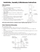
PUMP SPECIFICATIONS MODEL PFS ATEX Outer Tube Diameter 2” (51 mm) Discharge Type 1” hose barb Max. Specific Gravity 1.83 Max. Viscosity 500 cP 5°F Min. to 220°F Max. Min./ Max. Fluid Temperature 21°C Min. to 105°C Max. Wetted Materials 316 Stainless Steel, Perlast, PTFE, ETFE 5-5/16” 12-11/32” MODEL DIM A (in) DIM B (in) DIM C (in) DIM A (mm) DIM B (mm) DIM C (mm) PFS-27 27 29 41-3/8 685.8 737 1050.9 PFS-40 40 42 54-3/8 1016 1067 1381.1 PFS-48 48 50 62-3/8 1219.
ATEX COMPLIANCE The FTI PFS drum pump has been designed for use in hazardous environments. It meets the requirements set forth by EC directive 94/9/EC. This pump is designed to operate in zone 0 where explosive atmospheres are present. All three components (drum pump tube, motor and Static Protection Kit) must be properly installed. TEMPERATURE CLASSIFICATION The surface temperature of the PFS pump depends upon the temperature of the fluid being pumped.
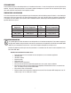
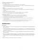
Installation, Assembly & Maintenance Instructions PFS Installation Installation 1. Remove the drum pump and motor from its packaging and inspect for shipping damage. 2. Spin the pump coupling to verify there is no binding. Verify that the black rubber coupling insert is firmly seated in the metal pump coupling. 3. Verify that the housing cover (item 16) is on tight (it has left hand threads). 4. Remove the (2) socket head screws and nuts from the motor/ motor mount. 5.
Ground wire attachment to motors: Electric Explosion Proof: 1. Screw #10-32 plated nut onto exposed machine screw in motor housing. 2. Attach #10 ring terminal from the end of the ground wire assembly to exposed machine screw in motor housing using #10-32 plated nut and #10 lock washer. Air Motor: 1. Remove one of the Allen head set screws from the motor mount. 2. Slide the ¼-20 x 5/8” long round head machine screw through the 1/4” ring terminal on ground wire assembly. 3.
Inspection 1. Check the housing cover (item 16), the impeller (item 15), and the impeller housing (item 13) for wear, rubbing, or damage from foreign objects. Replace if damaged. Note: The double impeller design of this pump is dependant on the impeller working correctly. Any damage to the impeller can cause pump failure. 2. Inspect the pump shaft (item 14) for wear in the bottom bearing (item 11) and the lip seal (item 4) areas. Replace the shaft if needed. 3.
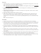
PFS ATEX SPARE PARTS EXPLODED VIEW 9
PUMP SPARE PARTS LIST ITEM 1 QTY 1 2 1 3* 1 4* 1 5 1 6 1 7 1 8* 2 9 1 10* 1 11* 1 12* 1 13 1 14 1 15* 1 16 1 DESCRIPTION PART NUMBER COUPLING INSERT J100014 COUPLING HALF J100012 BEARING ASSEMBLY A101110 LIP SEAL 1/4” LOCK WASHER #8 BRASS SCREW #8-32 X 1/4 BRASS PAN HEAD INTAKE TUBE ASSEMBLY 27” MODELS 40” MODELS 48” MODELS 60” MODELS 72” MODELS INNER TUBE O-RING PERLAST STAINLESS STEEL INNER TUBE 27” MODELS 40” MODELS 48” MODELS 60” MODELS 72” MODELS PTFE SHAFT SLEEVE 27”
M6A AIR MOTOR SPARE PARTS LIST & VIEW ITEM 1 2 3 4 5 6 7 8 QTY 1 1 1 1 1 1 2 1 9 2 10 2 11 1 12 13 14 1 2 1 DESCRIPTION PART NUMBER AIR MOTOR M101717 PIPE NIPPLE J100107 HEX REDUCER BUSHING J100057 BALL VALVE J100073 HOSE FITTING J100036 MUFFLER J100033 SET SCREW J100040 AIR MOTOR MOUNT M100013-3 CAP SCREW SOCKET HEAD NUT HEX HALF COUPLING J100023 J100024 A101621 LUBRICATOR J100035 PIPE NIPPLE J102463 FILTER J100034 Not shown: Air Motor Repair Kit J100060 11
M6XA AIR MOTOR SPARE PARTS LIST & VIEW ITEM 1 2 3 4 5 6 7 QTY 1 1 1 1 1 2 1 8 2 9 2 10 1 11 12 13 1 2 1 DESCRIPTION PART NUMBER AIR MOTOR M101720 PIPE NIPPLE J102463 BALL VALVE J100073 HOSE FITTING J100036 MUFFLER J100074 SET SCREW J100040 AIR MOTOR MOUNT M100013-4 CAP SCREW SOCKET HEAD NUT HEX HALF COUPLING J100023 J100024 A101620 LUBRICATOR J100035 PIPE NIPPLE J102463 FILTER J100034 Not shown: Air Motor Repair Kit J100075 12
M10X ELECTRIC MOTOR SPARE PARTS The “M10X” Series motor housing repair kit number is A101455. Repairs to any item other than the thermoplastic enclosure voids warranty. Note: Motor housing repair kits include motor covers, labels and screws to repair the motor should it be damaged.
M10X Switch Replacement Instructions Warning: Motor is ATEX certified and repair work must be performed by persons with competent electrical skills who are familiar with ATEX regulations. Warning: Make sure the machined aluminum surfaces of the explosion proof housing are not scratched or damaged during assembly/disassembly. Figure 1 1. Remove the screws from plastic motor housing and strain relief connector. See figure 1. 2. Carefully pry two plastic housings apart.
Ostrava-Radvanice -Physical Technical Testing Institute Ostrava-Radvanice Schedule (13) (1) EC-Type Examination Certificate (2) (14) Equipment or Protective Systems Intended for use in Potentially Explosive Atmospheres Directive 94/9/EC EC-Type Examination Certificate N° FTZÚ 04 ATEX 0293X (15) Description of Equipment or Protective System: (3) EC-Type Examination Certificate Number: A type PFS drum pump is used for transferring fluids from one container to another.
EC DECLARATION OF CONFORMITY Finish Thompson Inc. hereby declares that the following machines fully comply with the applicable health and safety requirements as specified by the EC Directives listed. This declaration is valid provided that the devices are fully assembled and no modifications are made to these machines.
EC DECLARATION OF CONFORMITY Finish Thompson Inc. hereby declares that the following machines fully comply with the applicable health and safety requirements as specified by the EC Directives listed. This declaration is valid provided that the devices are fully assembled and no modifications are made to these machines.
EC DECLARATION OF CONFORMITY Finish Thompson Inc.