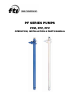
PF SERIES PUMPS PFM, PFP, PFV OPERATION, INSTALLATION & PARTS MANUAL
EU Declaration of Conformity Finish Thompson Inc. hereby declares that the following machine(s) fully comply with the applicable health and safety requirements as specified be the EC Directives listed. The product may not be taken into service until it has been established that the drive motor for the Drum and Container Pump complies with the provisions of all relevant EC Directives.
Introduction This manual pertains to the PF Series, specifically the PFP, PFM, and PFV plastic drum pumps. Finish Thompson Inc. thanks you for choosing our products. We believe the use of our products will be fully satisfactory. When properly installed and operated, your Finish Thompson motor and pump will provide long, trouble-free service; therefore, please read this manual carefully before carrying out any operations on the pump/motor unit.
Warranty, General Terms & Conditions 1. The following terms and conditions apply to the sale of machinery, components and related services and products, of Finish Thompson Inc. (hereinafter “the products”) 2. Finish Thompson Inc. (the manufacturer) warrants only that: a) its products are free of defects in material, design and workmanship at the time of original purchase; b) c) its products will function in accordance with Finish Thompson Inc. operation manuals; Finish Thompson Inc.
Safety 1. Introduction This manual contains all the information needed for the correct installation, use and maintenance of your new Finish Thompson pump. It should be read and understood by all the personnel involved in installation, operating and servicing of the pump before it is started. 2. Operator Qualification and Training The personnel in charge of the installation, the operation, and the maintenance of the pump must be qualified and able to perform the operations described in this manual.
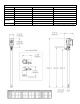
PUMP SPECIFICATIONS MODEL PFM MODEL PFP MODEL PFV 2” (51 mm) 2” (51 mm) 2” (51 mm) Discharge Spout Variable orifice barb fitting Variable orifice barb fitting Variable orifice barb fitting Discharge Thread 1-1/4” NPSM 1-1/4” NPSM 1-1/4” NPSM 1.83 1.83 1.83 2000 cP 2000 cP 2000 cP Outer Tube Diameter Max. Specific Gravity Max. Viscosity Min./ Max. Fluid Temperature 35°F Minimum to 160°F Maximum 35°F Minimum to 160°F Maximum 35°F Mininum to 120°F Maximum* (1.
INSTALLATION & MAINTENANCE INSTRUCTIONS Installation 1. 2. 3. 4. Remove the drum pump from its packaging and inspect for shipping damage. Turn the pump coupling to verify there is no binding. Verify the housing cover (item 21) is on tight (it has a left hand thread). Adjust the coupling so that the empty slots in the insert are at 3 and 9 o’clock with the pump discharge at 12 o’clock. 5.
Inspection 1. Check the housing cover (item 21), the impeller (item 20), and the impeller housing (item 18) for wear, rubbing, or damage from foreign objects. Replace if damaged. Note: The double impeller design of this pump is dependant on the impeller working correctly. Any damage to the impeller can cause pump failure. 2. Inspect the pump shaft (item 19) for wear in the bottom (item 16), center bearing (item 13) and the FKM lip seal (item 4) areas. Replace the shaft if needed. 3.
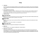
PFM/PFP/PFV SPARE PARTS EXPLODED VIEW Note: Items 4, 5, 9, 11 & 18 have been affected by design changes. If a repair involves any of these items, please refer to information found on page 8 of this manual.
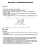
Impeller Housing change - PFM, PFP, PFV Series Old Style Impeller Housing Parts List Old Style Impeller Item Item 4 Beginning August 2010, Finish Thompson made a change to the impeller housing (item 18) on the plastic PF Series models (PFM, PFP, PFV). The change was phased in over several months and covers all the various tube lengths within these models.
PUMP SPARE PARTS LIST ITEM 1 2 3* 4* 5 9 10* 11 12* 13 14 15 16 17* 18* 19 20* 21* QTY 1 1 1 DESCRIPTION MODEL PFM PART NUMBER MODEL PFP MODEL PFV J100014 J100014 J100014 J100012 J100012 J100012 A101110 A101110 A101110 107592 107592 107592 107755-1 N/A 107755-1 N/A N/A 107755-2 107475-2 107475-3 107475-4 107475-5 107475-6 107475-2 107475-3 107475-4 107475-5 107475-6 107475-7 107475-8 107475-9 107475-10 107475-11 J100249 106519 105621 J100249 106519 105621 J100249 106519
ITEM QTY 22 1 23 1 24 1 25 (not pictured) 26 (not pictured) 1 1 DESCRIPTION DISCHARGE O-RING FKM EPDM PERLAST SPOUT 1” BARB (STANDARD) 3/4” BARB (OPTIONAL) 1” MNPT (OPTIONAL) DISCHARGE NUT FOR USE WITH 1” OR 3/4” BARB SPOUT FOR USE WITH 1” MNPT SPOUT ONLY MIDDLE INNER TUBE (PFM/PFP = POLYPROPYLENE, PFV = PVDF) 27” MODELS 40” MODELS 48” MODELS 60” MODELS 72” MODELS LOWER MIDDLE INNER TUBE (PFM/PFP = POLYPROPYLENE, PFV = PVDF) 27” MODELS 40” MODELS 48” MODELS 60” MODELS 72” MODELS MODEL PFM PART