SP10 SERIES SELF-PRIMING PUMPS ASSEMBLY, INSTALLATION AND OPERATION MANUAL
TABLE OF CONTENTS Model Number/Serial Number . . . . . . . . . . . . . . . . . . . . . . . . . . . . . . . . . . . . . . . . . . . . . . . . 3 Important Notice . . .. . .. . .. . .. . .. . .. . .. . .. . .. . .. . .. . .. . .. . .. . .. . .. . .. . .. . .. . .. 3 Chemical Reaction Disclaimer . . . . . . . . . . . . . . . . . . . . . . . . . . . . . . . . . . . . . . . . . . . . . . . . 3 Safety Precautions . . .. . .. . .. . .. . .. . .. . .. . .. . .. . .. . .. . .. . .. . .. . .. . .. . .. . .. . ..
Model Number and Serial Number Record the model number and serial number below for future reference. This is important information when ordering replacement parts or when technical assistance is required. The numbers are found on a label located on the motor adapter. MODEL NUMBER = ________________________ SERIAL NUMBER = ________________________ IMPORTANT NOTICE U.S.
WARNING: The pump and associated components are heavy. Failure to properly support the pump during lifting and movement could result in serious injury or damage to the pump and components. CAUTION: This pump should never be started without the 0.6 US gallon /77 oz. ( 2.7 liters) of priming fluid in the housing. If the pump has a PTFE, ceramic or silicon carbide bushing, IT CANNOT BE RUN DRY WITHOUT CAUSING DAMAGE TO THE PUMP.
Maximum Allowable Motor Power • Do not exceed the maximum power rating for the pump coupling. • Standard coupling for the SP10 is 10-pole & maximum 2 HP (1.5 kW). Priming Liquid Volume Initial filling (or refilling after maintenance) of the pump housing requires 0.6 US gallon / 77 oz. (2.7 liters) of liquid. Unpacking and Inspection Unpack the pump and examine for any signs of shipping damage. If damage is detected, save the packaging and notify the carrier immediately.
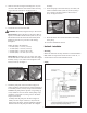
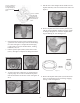
assembly. 8. Secure the pump to the motor with (4) 3/8” bolts, lock washers and flat washers (items 28, 29 & 30) using a 9/16” socket or wrench. Tighten to 240 in-lb (27.1 N-m). See figures 8 and 9. 5. Slide the outer drive magnet assembly (item 17) onto the motor shaft until the motor shaft contacts the snap ring in the bore of the drive. See figures 4 & 5. Figure 4 Figure 5 6. Secure the drive on the motor shaft. WARNING: Be careful, magnets will try to attract tools.
• The end of the pipe should be at least 2” (5.08 cm) for 1” pipe & 3” (7.6 cm) for 1½” pipe above the bottom of the suction tank. • If debris is in the suction tank, a strainer can be installed to help prevent foreign matter from entering the pump. The strainer must be periodically cleaned to prevent restriction. • It is recommended that a vacuum/pressure gage be installed in the suction piping. • For faster priming on installations with high lift, a foot valve is recommended.
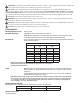
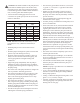
SP10 Priming Time Chart Impeller Diameter 1” (25.4 mm) Suction Piping 1.5” (38.1 mm) Suction Piping Motor Speed Motor Speed 3450 RPM 2900 RPM Feet of Lift (sec.) in. (mm) 5 10 15 20 3450 RPM Meters of Lift (sec.) 25 1.5 3.1 2900 RPM Feet of Lift (sec.) Meters of Lift (sec.) 4.6 6.1 7.6 5 10 15 20 25 1.5 3.1 4.6 6.1 7.6 455 4.18 (106.2) 10 35 65 100 140 10 40 80 160 240 25 60 100 150 210 30 75 145 255 4.00 (101.
washers (items 28, 29 & 30) securing the pump to the motor. See figure 10. Maintenance Recommended maintenance schedule The recommended maintenance schedule depends upon the nature of the fluid being pumped and the specific application. If the pump is used on a clean fluid, it is recommended that the pump be removed from service and examined after six months of operation or after 2,000 hours of operation.
9. Pull the inner volute straight off. Be careful since the impeller shaft may come out with the inner volute. See figure 17. Insert one screwdriver under this bolting location. Insert approximately 3/4” (19 mm) until it hits the barrier. Insert one screwdriver under this bolting location.Insert approximately 3/4” (19 mm) until it hits the barrier. Figure 12 Figure 17 10. Remove impeller/inner drive assembly (items 8, 8A, 9 & 9A). Inspect impeller and drive for signs of wear or damage. See figure 18.
12. Pull on one of the 3 prongs to remove the barrier (item 11) from the clamp ring and motor adapter (items13 & 15). NOTE: Prongs are sharp. Use a glove or rag for better grip. Motor adapters have an o-ring seal between the barrier and adaptor so fit may be snug. See figure 21. Inspect the inside and outside of the barrier for signs of rubbing. Thrust Ring Replacement 1. The thrust ring (item 8A) is held in-place with a snap fit with a ridge.
4. Install barrier into motor adapter/clamp ring assembly. NOTE: If removed, reinstall the o-ring (item 12), lubricate with a chemically compatible lubricant, and install in the groove in the clamp ring before installing the barrier. See figure 33A. Lubricate the back of the barrier with a chemically compatible lubricant and push it straight down into place. See figure 33B. Note: Barrier can only be installed in one position. The barrier prongs should be placed in the 11:00, 2:00 and 5:00 o’clock positions.
9. Install the separator plate (item 6) by lining up the bottom opening of the inner volute with the opening in the plate. Line up the slots in the separator plate with the notches in the inner volute. See figure 38. 10. If the inner volute o-ring was removed previously, lubricate the inner volute o-ring (item 5) with a chemically compatible lubricant, and install it in the groove on the round suction nozzle in the center of the inner volute. See figure 39. Figure 34 Figure 35 8.
• Leak in suction piping • Suction pipe not submerged enough (causing a vortex or exposing the end of the suction pipe) • Lift exceeds pump ability (see Capabilities section) • Suction pipe diameter too large • Specific gravity or local atmospheric pressure (altitude/ elevation) not accounted for in lift calculations • Mis-match of inner volute and impeller diameter • Inner volute o-ring chemically attacked, cut, brittle, etc.
and is in lieu of any other warranties, either expressed or implied. This warranty does not apply to normal wear of the product or components. This warranty does not apply to products or parts broken due to, in whole or in part, accident, overload, abuse, chemical attack, tampering, or alteration. The manufacturer accepts no responsibility for product damage or personal injuries sustained when the product is modified in any way.
SP10 Spare Parts List Item Qty 1 1 2 2 2A 2 3 1 4 1 5 1 6 1 7 1 8 1 8A 1 Pump Material Polypropylene PVDF Description Housing NPT Threads BSP Threads Steel Flanges Fiberglass Flanges Unions Fill/Drain Plug 106564 106564-2 106964-1 106964 106965 106564-1 106564-3 106964-3 106964-2 106965-1 106143 106143-1 Fill Plug O-Ring EPDM FKM Discharge O-Ring (BSP Housings Only) EPDM FKM Housing O-Ring EPDM FKM Inner Volute O-Ring EPDM FKM Separator Plate 106154 106155 106304 106303 106299 1
SP10 Spare Parts - continued Item Qty 9 1 9A 1 10 1 11 1 12 1 13 1 14 1 15 1 16 1 Pump Material Polypropylene PVDF Description Impeller Drive 6-pole w/ carbon bushing 8-pole w/ carbon bushing 10-pole w/ carbon bushing 6-pole w/ sIlicon carbide bushing 8-pole w/ sIlicon carbide bushing 10-pole w/ sIlicon carbide bushing 6-pole w/ alumina ceramic bushing 8-pole w/ alumina ceramic bushing 10-pole w/ alumina ceramic bushing 6-pole w/ PTFE bushing 8-pole w/ PTFE bushing 10-pole w/ PTFE bushi
SP10 Spare Parts - continued Item Qty 17 1 17A 1 17B 2 18 1 Pump Material Polypropylene PVDF Drive Magnet Assembly with Retaining Ring (56C frame also includes set screws) 56C frame, 6-pole 106283 56C frame, 8-pole 106283-1 56C frame, 10-pole 106283-2 143/145TC frame, 8-pole 106283-4 143/145TC frame, 10-pole 106283-5 63 frame, 6-pole 106289 63 frame, 8-pole 106289-1 63 frame, 10-pole 106289-2 71 frame, 6-pole 106286 71 frame, 8-pole 106286-1 71 frame, 10-pole 106286-2 80 frame, 8-pole 106292-1 80
Hardware - All SP10 Models Item Qty 19 6 20 21 22 23 24 25 6 6 4 4 4 1 26 1 27 1 28 4 29 30 4 4 31 4 32 4 33 4 34 4 Description Stainless Steel Titanium J102789 106308 J102282 J103847 105767 105768 105767 105768 J102282 J103847 105770 105770 106314 106312 105765 105770 106315 106313 105766 105771 106322 106320 J100672 J102282 106323 106321 J104203 J103847 106318 106316 105767 105722 106319 106317 105768 105773 J100114 106311 J100115 J104206 J100128 J104207