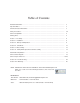
Table of Contents Model/Serial Number......................................................................................................................... 3 Important Notice................................................................................................................................ 3 Chemical Reaction Disclaimer........................................................................................................... 3 Safety Precautions..........................................
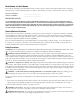
Model Number and Serial Number Record the model number and serial number below for future reference. This is important information when ordering replacement parts or when technical assistance is required. The numbers are found on a label located on the motor adapter. MODEL NUMBER = ________________________ SERIAL NUMBER = ________________________ IMPORTANT NOTICE U.S.
WARNING: Chemical Hazard. This pump is used for transferring many types of potentially dangerous chemicals. Always wear protective clothing, eye protection and follow standard safety procedures when handling corrosive or personally harmful materials. Proper procedures should be followed for draining and decontaminating the pump before disassembly and inspection of the pump. There may be small quantities of chemicals present during inspection.
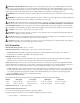
• 8-pole coupling = 3 horsepower (2.2 kW) • 10-pole coupling = 5 horsepower (4 kW) Priming Liquid Volume Initial filling (or refilling after maintenance) of the pump housing requires 1 US gallon (3.8 liters) of liquid.
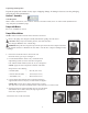
Unpacking and Inspection Unpack the pump and examine for any signs of shipping damage. If damage is detected, save the packaging and notify the carrier immediately. Section I - Assembly Tools Required: Metric socket or wrench set, 9/16” socket or wrench, 8 mm Allen wrench, and 3/16” Allen wrench (NEMA motors only) and pliers (for fill/drain plugs). Pumps with Motors Proceed to “Installation” Section Pumps Without Motors NOTE: 184TC and 100/112 frame motors must have motor feet. 1.
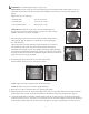
WARNING: Be careful, magnets will try to attract tools. Metric Motors: Secure the drive to the motor shaft using bolt, lock washer and flat washer (items 19, 20, 21). Thread the bolt into the end of the motor shaft (while holding the outer drive to prevent it from turning). See figure 6. Tighten the bolt to the following: * 80 frame (M6) = 90 in-lb (10.2 N-m) * 90 frame (M8) = 130 in-lb (14.7 N-m) * 100/112 frame (M10) = 240 in-lb (27.
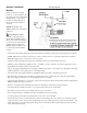
Section II - Installation SP Piping Diagram Mounting Pump foot should be securely fastened to a solid foundation. If the pump was received with plastic shipping shims, it is possible to use these as additional support for the motor feet (though not required). NOTE: B5 pumps with 100/112 frame do not include a pump foot. CAUTION: The NPSH available to the pump must be greater than the NPSH required. The amount of lift, frictional pipe loss and vapor pressure must be calculated into the application.
• NOTE: If a check valve is used in the discharge line, it must be placed at a distance at least equal to the maximum suction lift from the pump. If this cannot be done, an air vent must be provided in the discharge line. • If flexible hose is preferred over pipe, use a reinforced hose rated for the proper temperature, pressure and is chemically resistant against the fluid being pumped. • The suction valve must be completely open to avoid restricting the suction flow.
Section IV - Shutdown • Turn off the motor. NOTE: When the pump is stopped without a check valve in the piping, liquid will flow through the pump returning to the suction source. The SP design allows enough liquid to be retained in the housing to allow repriming without having to refill with liquid. Flush Systems CAUTION: Some fluids react with water; use compatible flushing fluid. 1. Turn off the pump. 2. Completely close the suction and discharge valves. 3.
prior to opening the pump. Allow the pump to reach ambient temperatures prior to performing maintenance. 2. For pumps with motors 2 horsepower (1.5 kW) or smaller, securely clamp the pump feet to the bench. Remove the (4) bolts, lock washers and flat washers (items 22, 23, 24 ) securing the pump to the motor. See figure 9 Firmly grab the motor and pull straight back to disengage the motor and pump. See figure 11 Figure 9 Figure 12 Figure 11 For pumps with motors 3 horsepower (2.
Figure 16 Figure 17 Figure 18 9. Pull the inner volute straight off. Be careful, the impeller shaft may come out with the inner volute. See figure 19. Inspect inner volute for signs of wear or damage. Look for signs of rubbing or cracking on the ring or damage to the front shaft support. 10. Remove impeller/inner drive assembly (items 7A, 7, 8, 8A). Inspect impeller and drive for signs of wear or damage. Look for signs of rubbing, damage and wear to the impeller and inner drive. See figure 20.
Thrust Ring Replacement 1. Thrust ring (item 7A) is held in-place with a snap fit with a ridge. Using a razor knife or side cutters, cut a notch out of the thrust ring. Pull ring up and out of the holder. See figures 25 and 26. 2 To reinstall, align the two flats on the thrust ring with the flats in the bore of the impeller. Using a piece of wood press into place using an arbor press until the thrust ring is completely seated in the impeller. Figure 25 Figure 26 Bushing Replacement 1.
Section VI - Clamp Ring Replacement and Reassembly 1. Inspect the clamp ring. If clamp ring requires replacement, it is recommended to remove the plastic foot (item 15) first. NOTE: 100/112 frame B5 adapters do not use the foot. See figures 32 and 33. Remove the four (4) M6 bolts (items 28 and 28A). Figure 33 Figure 32 2. Remove the five (5) M8 bolts, lock washers and flat washers (items 34, 33, and 32) from the clamp ring (item 12B). See figure 34. Remove the clamp ring from the motor adapter.
5. For 56C, 145TC and 80 frame B14, re-install the plastic foot (item 15) to the motor adapter (item 12D). Use the longer M6 bolts, lock washers and flat washers (items 28A, 29 and 30) for the front bolt holes towards the clamp ring. See figure 40. Use the shorter M6 bolts, lock washers and flat washers (items 28, 29 and 30) for the rear bolt holes towards the motor face. NOTE: Nuts (item 31) are glued Figure 41 Figure 40 into the rear of the motor adapter to help with the installation of the rear bolts.
Figure 47 Figure 48 12. Install the separator plate (item 4) by lining up the bottom opening of the inner volute with the opening in the plate. Line up the slots in the separator plate with the notches in the inner volute. See figure 49. 13. Lubricate the inner volute o-ring (item 5) with a chemically compatible lubricant and install in the groove on the round suction nozzle in the center of the inner volute. See figure 50. Figure 49 Figure 50 14. Lubricate the inside of the gooseneck. See figure 51.
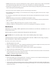
SP11 / SP15 PART NUMBER EXPLANATION NOTE: Pump end includes wetted components, drive magnet and motor adapter. The wet end incudes wetted components only. Part Number Explanation The base model number contains standard components. Where standard components are not suitable, add the alternative component code after the base model number to substitute components. Example: SP11-E-U-14 is constructed of the listed base model components except it has an EPDM o-rnig, union connections, and a 145TC motor adapter.
SP11/15 PARTS DRAWING SP11/15 Parts Diagram 11 10 8A 8 9 7 7A 6 2 18 17 4 5 1 26 25 16 23 3 33 12B 12C 14 24 22 12D 3A 27 34 32 13B 12A 19 31 21 20 28 29 28A 30 15 18 13A
SP11/SP15 Spare Parts List Item Qty 1 1 2 1 3 2 3A 2 4 1 5 1 6 1 7 1 7A 1 SP11 Pump Material PP PVDF Description Housing NPT threads BSP threads Steel flanges Fiberglass flanges Unions Discharge O-Ring (BSP Threaded Housings Only) EPDM FKM Fill/Drain Plug 105862 105862-2 105866 105866-1 105867 SP15 Pump Material PP PVDF 105862-1 105862-3 105866-2 105866-3 105867-1 105862 105862-2 105866 105866-1 105867 105862-1 105862-3 105866-2 105866-3 105867-1 105918 105919 106143 Fill Plug O-
SP11/15 Spare Parts List - cont.
SP11/15 Spare Parts List - cont.
Hardware - All SP11/15 Models Item Qty 16 8 17 8 18 8 19 1 20 1 21 1 22 4 23 4 24 4 25* 4 26* 4 27* 4 28 2 28A 29 30 31 32 2 4 4 2 5 Description Stainless Steel Titanium 106210 106211 105757 105758 105722 105773 105765 105770 105774 105766 105771 105775 J100672 J102282 J100115 J104203 J103847 J104206 105767 105722 J101360 105768 105773 106200 J103118 J100114 105752 106311 J100115 J104206 J100128 J104207 J103782 J103780 105770 105770 105761 105764 105771 10
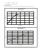
Hardware - cont. Item Qty 33 5 34 5 Description Clamp Ring Lockwasher Stainless Steel Titanium J102282 J103847 J103662 107285 Clamp Ring Bolt *For IEC B5 frame pumps: Hardware is to be supplied by customer due to variations in B5 frame motors. SP11/15 Impeller Assemblies Thrust Impeller Ring Material SP11 PTFE SiC Polypro PVDF Polypro PVDF Thrust Impeller Ring Material SP15 PTFE SiC #1 #2 #3 #4 #5 #6 #7 #8 #9 #10 4.63" 4.38" 4.13" 3.88" 3.63" 5.25" 5.00" 4.75" 4.50" 4.
Section VII - Troubleshooting General Notes: • Cold water can contain dissolved air. Under high lift applications, the air can come out of solution blocking suction passages. This can lead to lack of priming, slow priming or low flow rates. Do not pump liquids containing ferrous metal fines. • If magnets de-couple, stop pump immediately. Operating the pump with the magnets de-coupled will eventually weaken the magnets.
Primes Slowly • Mismatch of inner volute and impeller diameter • Suction pipe diameter too large (larger than 1 1/2”) • Closed discharge valve (valve should be open) • Inner volute o-ring chemically attacked, cut, brittle, etc. Excessive Power Consumption • Head lower than rating • Excessive flow • Specific gravity or viscosity too high.
Part Number 107404, Rev11, 2/14/2014 Order fax: 814-459-3460 Tech Service: 800-888-3743 Literature ID No.